Refer to the following sections for information on tool settings common to all the Artisan-based tools.
Use the settings in this section to define the brush stamp shape, size, orientation.
If you are using a stylus, set the upper or maximum possible radius for the brush. No matter how hard you press the stylus, the brush radius will not exceed this radius. If you are not using a stylus, this setting defines the radius for the brush. The maximum value is 50 when using the slider; but if you use the hotkey (press b and drag the left mouse button) you can set a value higher than 50.
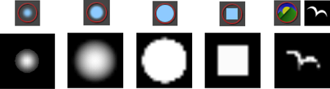
Click a brush profile. This determines the shape of the area affected by the selection.
In addition to the four preset brush profiles, you can select an image to define the brush stamp profile. Maya provides 40 additional brush shapes in the brushShapes directory, which is located in Maya's default installation directory.You can create your own shapes using any file format supported by Maya. Maya uses the luminance values of the image and scales the image to 256x256.
To select an image, click the Browse button, select the shape and click Open. Adjust the Stamp Spacing to get the effect you want.

To select the last opened image, click the icon to the left of the Browse button. If you select an image file provided with Maya in the brushShapes directory, this icon changes to show what the shape is.
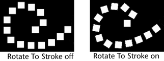
Determines the alignment of brush shapes that are not uniformly round. Turn this option on to align the stamp shape relative to the direction you move the brush. Turn this option off to align the stamp shape relative to the up vector. The stamp shape retains its orientation when you change the view.
Use the options in this section to define how brush stamps are applied when you paint a stroke
When this option is off (the default), the brush is oriented along the surface. When this option is on, the brush is oriented on the view plane and the stamp is projected on the selected surface.
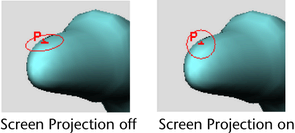
You will typically want to leave this option off if you are using an Artisan brush. You may want to turn it on when using an Artisan brush if the surface is very convoluted.
If you are using a Autodesk®Paint Effects™ brush (3D Paint Tool only), turn it on if:
Using Screen Projection may produce smearing where the surface is nearly perpendicular to the screen and performance may be slower. Simply tumble to make the surface approximately parallel to the screen.
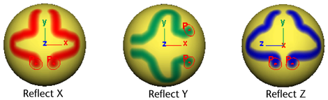
Turn on this checkbox for reflections.
Reflection is disabled for the Paint Skin Weights Tool. Skin > Edit Smooth Skin > Mirror Skin Weights can be used as an alternative method to do reflection of the skin weights.
(The Reflection option must be checked to use this option.)
By default the reflection axis is the center of the selection's bounding box. For the reflection axis to be the origin, turn on this checkbox. This is useful if the model is not entirely symmetrical; for example, a creature with a tail that is curled to one side.
This is available for the Sculpt Geometry Tool only. Turn Invert Reference Vector on to invert the direction of the reference vector of the reflected brush. For details on setting reference vectors, see Mesh > Sculpt Geometry Tool.
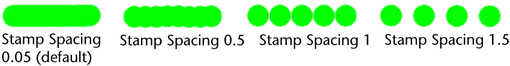
Clicking the brush on a surface creates a stamp. A brush stroke is made up of many overlapping stamps. You can set how the stamps overlap. If you set Stamp Spacing to 1, the edges of each stamp just touch each other. If you set the spacing to be greater than one, there will be spaces between the stamps. If you set the spacing to be less than one, the stamps will overlap.
For the Paint Selection Tool and Sculpt Geometry Tool only. Type the MEL command and parameters you want to run when you begin a stroke, before the stroke actually starts. For example, for the Sculpt Geometry Tool, you can specify a command that changes the display smoothness for the selected object to fine:
 .
.
ppolySubdivideFacet -dv 1 -m 0 -ch 1
Use the settings in this section to define the effects of stylus pressure on your strokes when you use a stylus and pressure sensitive tablet. For details on setting stylus pressure, see Set stylus pressure.
Use these settings to affect stylus pressure when you are using a Paint Effects brush with the 3D Paint Tool. For details, see Set up to paint in 3D in the Paint Effects and 3D Paint Tool guide.
Use the settings in the Attribute Maps section to import and export attribute value maps. For details on mapping, see Map attributes.
You cannot use the Paint Skin Weights Tool to import and export skin weight maps. Instead, use the Import Skin Weight Maps and Export Skin Weight Maps commands on the Skin > Edit Smooth Skin menu.
Use the options in this section to import attribute maps. For more details, see Import attribute maps.
Use the options in this section to export attribute values (created with the following tools) to an attribute map: Paint Selection, Paint Attributes, Paint Cluster Weights, Paint Jiggle Weights, Paint Soft Body Weights, Paint Fluids, Paint Vertex Color Tool, Paint Fur Attributes, Paint Cloth Properties, Paint (Cloth) Collision Properties and Paint Hair Tools. For more details, see Export attribute maps.
Define how the brush and surface display.
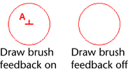
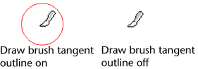
Turn this on to display the paint tool’s brush outline when painting on a surface. Turn this off to display only the brush pointer when painting on a surface. Draw brush while painting is off by default.
If you notice slow interaction while you paint, try turning this option off. This greatly improves performance on graphic cards without overlay planes.
Turn this on to display the paint tool’s brush outline when you move the pointer over the selected surface. If this setting is off, you will not see the brush outline when you move the pointer over the selected surface.
You can change the brush outline color to one that provides the best contrast with the surface you are painting. For more information, see Change the brush outline color.
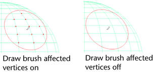
For the Sculpt Geometry Tool only. Only available when Screen Projection is off in the Stroke section.
Turn this on to highlight the vertices the Sculpt Geometry Tool is affecting as you pass the brush over the selected surface. For more information on the Sculpt Geometry Tool, see Mesh > Sculpt Geometry Tool in the Polygon modeling guide.
For Paint Attributes, Paint Cluster Weights, Paint Jiggle Weights, Paint Skin Weights, Paint Soft Body Weights, Paint Set Membership, Paint Fur Attributes, and Paint Hair Tools only.
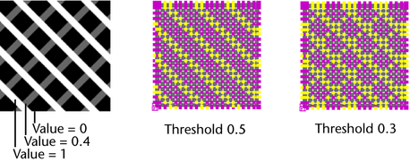
Turn this option on to display surface attributes as grayscale values. This helps you see the area as you paint and helps identify what the values are (smaller values are darker, larger values are lighter). To display color feedback, you must turn on smooth shading in Maya.
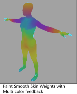
For Paint Skin Weights Tool only. Turn on this setting to view the distribution of painted skin weights on your bound geometry as multi-color feedback. The colors that appear on your bound pieces of geometry correspond to the colors of their skeletons’ joints and bones, and they indicate the areas of skin each of their joints affect. You can view Multi-color Feedback in the scene view when in Vertex mode or when using the Paint Skin Weights Tool.
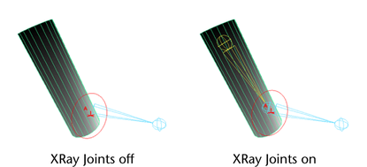
This option is also available from the panel menus. See Shading > X-Ray Joints.
Turn this option on to have wireframe joints display on top of the mesh you are painting. This lets you view the mesh in a shaded mode and easily select wireframe Influence objects without switching between wireframe and shaded views.
For Paint Attributes, Paint Cluster Weights, Paint Jiggle Weights, Paint Skin Weights, Paint Soft Body Weights, Paint Fur Attributes, and Paint Hair Tools only. Sets the value at which the minimum color displays. This is useful if your attribute values are very close to each other, making the color feedback display too subtle to detect.
For Paint Attributes, Paint Cluster Weights, Paint Jiggle Weights, Paint Skin Weights, Paint Soft Body Weights, Paint Fur Attributes, and Paint Hair Tools only. Sets the value at which the maximum color displays. This is useful if your attribute values are very close to each other, making the color feedback display too subtle to detect.
This section is unique to the Paint Scripts Tool. For more information, see Set Paint Scripts Tool settings or see artUserPaintCtx in the MEL Command Reference.
 Except where otherwise noted, this work is licensed under a Creative Commons Attribution-NonCommercial-ShareAlike 3.0 Unported License