Shader Type Overview
There are many types of shaders, all of which can be substituted
by user-written shaders:
- material shaders
- describe the visible material of an object. They are the only
mandatory part of any material description. Material shaders are
called whenever a visible ray (eye ray, reflected ray, refracted
ray, or transparency ray) hits an object. Material shaders have a
central function in mental ray.
- volume shaders
- are called to account for atmospheric effects encountered by a
ray. The state (see below) distinguishes two types of volume
shaders: the standard volume shader that is called in most
cases, and the refraction volume shader that is taken from
the object material at the current intersection point, and becomes
the standard volume shader if a refraction or transparency
ray is cast. Many material shaders substitute a new standard
volume shader based on inside/outside calculations. Volume
shaders, unlike other shaders, accept an input color (such as the
one calculated by the material shader at the last intersection
point) that they are expected to modify.
- light shaders
- implement the characteristics of a light source. For example, a
spot light shader would use the illumination direction to attenuate
the amount of light emitted. A light shader is called whenever a
material shader uses a built-in function to evaluate a light. Light
shaders normally cast shadow rays if shadows are enabled to detect
obscuring objects between the light source and the illuminated
point.
- shadow shaders
- are called instead of material shaders when a shadow ray
intersects with an object. Shadow rays are cast by light sources to
determine visibility of an illuminated object. Shadow shaders are
basically light-weight material shaders that calculate the
transmitted color of an object without casting secondary or shadow
rays. Frequently, material shaders are written such that they can
also be used as shadow shaders.
- environment shaders
- are called instead of a material shader when a visible ray
leaves the scene entirely without intersecting an object. Typical
environment shaders evaluate a texture mapped on a virtual infinite
sphere enclosing the scene (virtual because it is not part of the
scene geometry).
- photon shaders
- are used to propagate photons through the model in order to
simulate caustics and global illumination. Photon shaders are
used in a preprocessing step in which photons are emitted from the
light sources into the model (just as a real light source emits
photons into the world). Each photon is traced through the scene
using a technique called photon
tracing which is similar to ray
tracing. As with ray
tracing a photon is reflected of a specular mirror surface in
the mirror direction. The most important difference is the fact
that the photon shader modifies the photon energy before
reflecting the photon unlike ray
tracing which traces a ray and then modifies the result
accordingly (for example multiplies it with the specular reflection
coefficients). Photon shaders also store information about the
incoming photon in a global photon
map which contains all photons stored in the model. This photon
map is then used by the material shaders during the rendering step
(ray tracing step) to simulate
caustics and global illumination. Frequently, material shaders are
written such that they can also be used as photon shaders (and also
shadow shaders).
- photon volume shaders
- are similar to photon shaders in the same way that volume
shaders are similar to material shaders: they compute indirect
light interactions in volumes, such as volume scattering.
- photon
emitter shaders
- are used to control the emission of photons from a light
source. Combined with the light shaders it is possible to simulate
complex light sources with complex emission characteristics. Photon
emitters are only used if caustics or global illumination are enabled, to
construct a photon map before the
actual rendering takes place.
- texture shaders
- come in three flavors: color, scalar, and vector. Each
calculates and returns the respective type. Typical texture shaders
return a color from a texture image after some appropriate
coordinate transformation, or compute a color at a location in 3D
space using some sort of noise function. Their main purpose is to
relieve other shaders, such as material or environment shaders,
from performing color and other computations. For example, if a
marble surface were needed, it should be written as a texture
shader and not a material shader because a texture shader does not
have to calculate illumination by light sources, reflections, and
so on. It is much easier to write a texture shader than a material
shader. mental ray never calls a texture shader directly, it is
always called from one of the other types of shaders.
- displacement shaders
- are called during tessellation of polygonal or free-form
surface geometry, a procedure that creates triangles to be
rendered. Displacement shaders are called to shift the created
vertices along their normals by a scalar distance returned by the
shader. mental ray supports approximation controls that allow
adjusting the tessellation to better resolve curvature introduced
by displacement shaders.
- geometry shaders
- are run before rendering begins. They create geometry
procedurally by using a function call library that closely follows
the .mi scene description language. Unlike displacement shaders,
which are called once per vertex, geometry shaders are responsible
for creating an entire object or object hierarchy (each of which,
when tessellated later, can cause displacement shader calls).
- contour shaders
- come in four different flavors: contour store shaders, contour
contrast shaders, contour shaders, and contour output shaders. For
details see section contour.
- lens shaders
- are called when a primary ray is cast by the camera. They may
modify the eye ray's origin and direction to implement cameras
other than the standard pinhole
camera, and may modify the result of the primary ray to
implement effects such as lens flares.
- output shaders
- are different from all other shaders and receive different
parameters. They are called when the entire scene has been
completely rendered and the output image resides in memory. Output
shaders operate on the output image to implement special filtering
or compositing operations. Output shaders are not associated with
any particular ray because they are called after the last ray is
completed.
- lightmap shaders
- can be attached to materials to scan the surface of an object,
collecting data and optionally writing a writable texture to disk. This can be
used to "bake" illumination solutions into a texture, for
example.
- state shaders
- can be attached to the options block. They are called on four
occasions: Once a state is created, once a state is destroyed, just
before the first regular shader for a sample is called, and just
before the computed sample is written to the frame buffer. These
four cases may be distinguished by different constants passed to
the shader. These shaders may be used to manipulate the state of
mental ray. A common application is to add some data to the state
that is needed by various shaders during rendering.
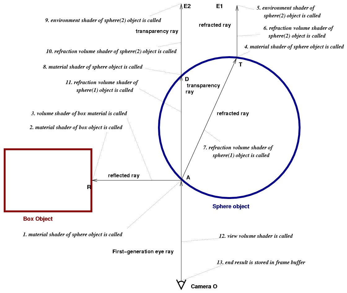
The following diagram illustrates the path of a
ray cast by the camera. It first intersects with a sphere at point
A. The sphere's material shader first casts a reflection ray that
hits a box, then a refraction ray that intersects the sphere at its
other side T, and finally it casts a transparency ray that also
intersects the sphere, at D. (This example is contrived, it is very
unusual for a material shader to cast both a refraction and a
transparency ray.) The same material shader is called at points A,
T, and D. In this example, the reflection trace depth may have
prevented further reflection rays to be cast at T and D.
The annotations set in italics are numbered; the events
described happen in the sequence given by the numbers.
Since material shaders may do inside/outside calculations based
on the surface normal or the parent state chain (see below), the
volume shaders are marked (1) and (2), depending on whether the
volume shader left by A or by T/D in the refraction volume
field of the state. The default refraction volume shader is the one
found in the material definition, or the standard volume shader if
the material defines no volume shader. For details on choosing
volume shaders, see the section on writing material and volume
shaders. Note that the volume shaders in this diagram are called
immediately after the material shader returns.
mental ray 3.0 also supports a autovolume mode, enabled in the options
block with autovolume on. In this mode, mental ray finds
out which volumes the camera is in by casting a single ray to
infinity, and offers four shader API functions that tell the shader
which volumes the current intersection point is in. Shader
declarations may contain autovolume levels that define which
volumes mix and which volumes displace others.
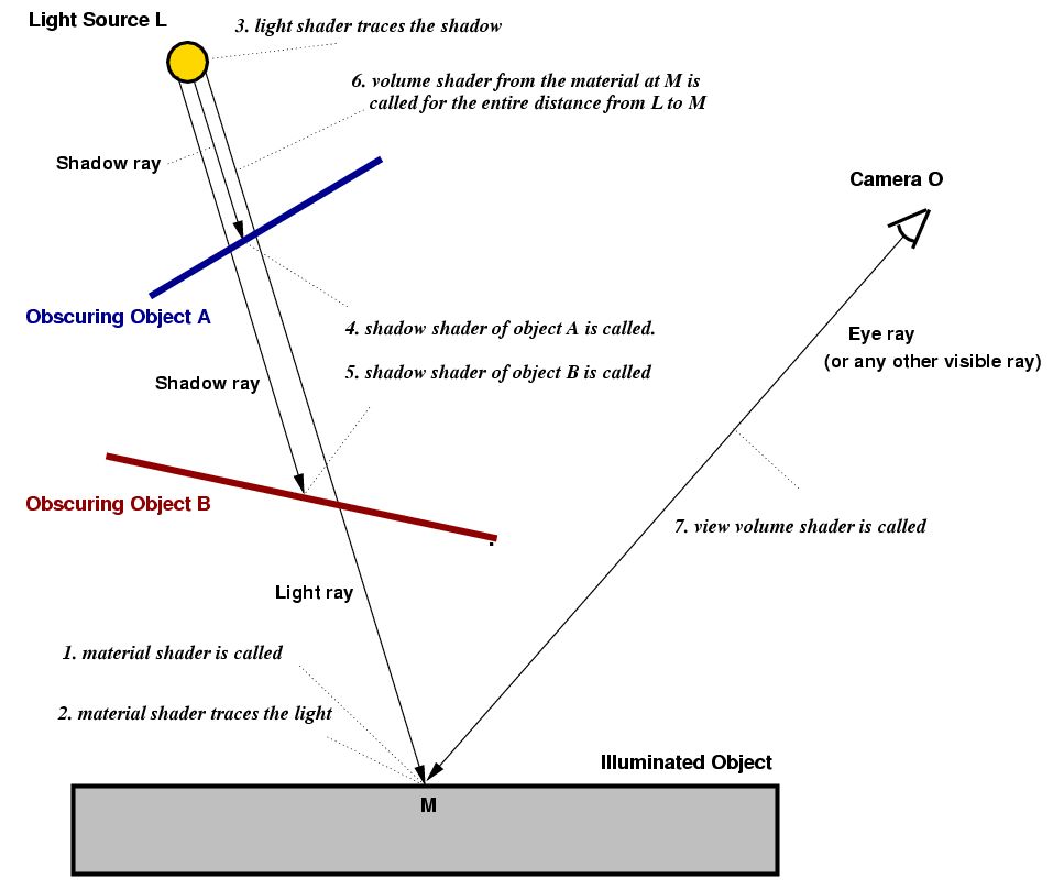
The next two
diagrams depict the situation when the material shader at the
intersection point M requests a light ray from the light source at L,
by calling a function such as mi_sample_light. This results in
the light shader of L to be called. No intersection testing is done
at this point. Intersection testing takes place when shadows are
enabled and the light shader casts shadow rays by calling
mi_trace_shadow. This function is called only once but may
result in more than one shadow shader call. There are four
different modes for shadow casting, listed in the order of
increased computational cost:
- shadow off
No shadows are computed, and no shadow shaders are called. Call to
mi_trace_shadow return immediately without modifying the
result color.- shadow on
For each obscuring object (A and B), a shadow ray is generated with the origin
L and the intersection point A or B, and the shadow shaders of objects A and B are
called to modify the light emitted by the light source based on the
transparency attributes of the obscuring object. No shadow ray is
generated for the segment from B to M because no other obscuring
object whose shadow shader could be called exists. Although shadow
rays always go from the light source towards the illuminated point
in this mode, the order in which the shadow shaders are called is
undefined. If an object without shadow shader is found, or if a
shadow shader returns miFALSE, it is assumed that no light
reaches the illuminated point and the search for more obscuring
objects is stopped (although the light shader has the option of
ignoring this result and supplying some light anyway). See the
first diagram below. The volume shader of the illuminated object M
is applied to the entire distance between M and L.- shadow sort
Same as the previous method, but shadow shaders are called in
distance order, object closest to the light source first. In the
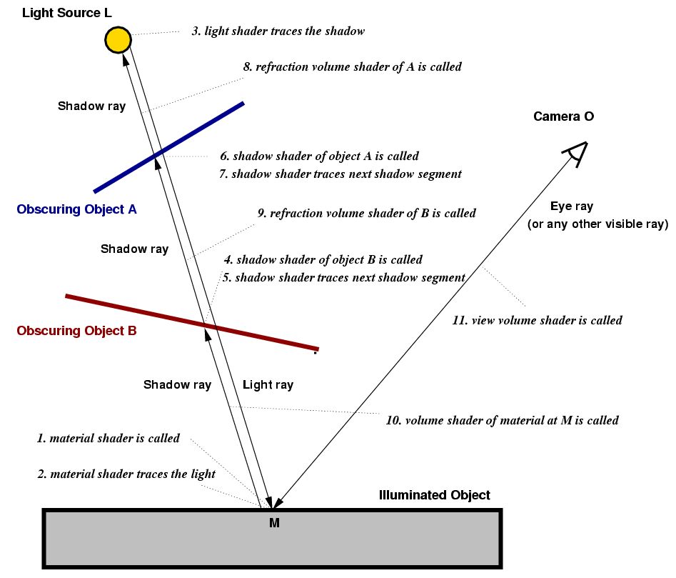
first diagram, steps 4 and 5 may be reversed.- shadow segments
This mode is more sophisticated than the others. Shadow rays become
similar to visible rays; they travel in segments from the
illuminated point to the first obscuring object, then from there to
the next obscuring object, and so on until the light source is
reached. This means that shadow rays travel in the opposite
direction, and one shadow ray's end point becomes the next shadow
ray's origin. Volume shaders are called for each of these segments,
and every shadow shader must perform inside/outside calculations to
store the correct volume shader in state→volume
much like material shaders to. This mode is preferred if volume
effects should cast shadows.
Note that the shadow segment mode requires complex shadow
shaders to behave differently. Every shadow shader must be able to
work with all these modes, so shadow shaders that deal with volumes
or depend on the ray direction must test
state→options→shadow to determine the mode.
In case an incorrectly implemented shadow shader fails to call
mi_trace_shadow_seg to evaluate other shadows, mental ray
will call mi_trace_shadow_seg and then call the shadow
shader again, thus simulating the effect.
The first diagram shows the ray casting order and the ray
directions for the shadow on and shadow sort
modes:
The next diagram shows the same situation in shadow
segments mode:
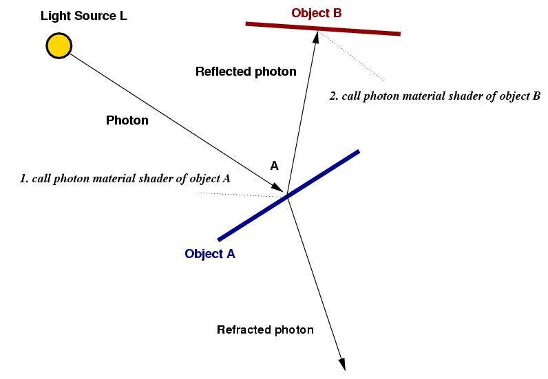
The following diagram illustrates the path of a photon shot from
the light source in the caustics
or global illumination
preprocessing phase. First a photon is traced from the light
source. It hits object A, and the photon material shader of object
A is called. The photon material shader stores energy at the
intersection point and determines how much energy is reflected and
how much is refracted, and the directions of reflection and
transmission. It then traces a new photon from A, in the reflection
direction, or in the transmission direction, or both. The reflected
photon hits object B, and the photon material shader of object B is
called. The photon material shader of object B stores energy at the
intersection point and shoots a new photon.
The remainder of this chapter describes how to write all types
of shaders. First, the concepts of ray tracing state parameter passing
common to all shaders are presented, followed by a detailed
discussion of each type of shader.
Copyright © 1986-2010 by
mental images GmbH