


Controlling auto-resized
boundaries
When using Auto Resize to set your fluid container size, there are ways to control how much the container boundaries resize. Controlling the bounders of your fluid ensures that your it does not expand too much or stop it from resizing into specific areas of your scene. Depending on your fluid effect, you can use one of the following methods to control auto-resized boundaries.
Use the Max Resolution attribute
You can use the Max Resolution attribute to set the maximum number of voxels that a fluid container can increase when it resizes. The maximum number of voxels in a resized fluid container is the set Max Resolution value cubed.
For example, if Max Resolution is set to 10, then the total resolution of the fluid cannot be greater than that of a 10×10×10 fluid. This means that you can have a 3D fluid with a Resolution of 5×20×10, but not 6×20×10, or you can have a 2D fluid with a Resolution of 20×50, but not 21×50.
Max Resolution also sets how large the side of a fluid container can be. The maximum size along a side of the container is 300 voxels or twice the Max Resolution value, whichever is larger.
See Max Resolution.
If Resize Closed Boundaries is off, any boundaries that are closed will remain fixed, as defined by the Container Properties Boundary X, Boundary Y, and Boundary Z attributes. This means that, when Resize Closed Boundaries is off, you use the Boundary X, Y, and Z attributes to specify along which axis you want the container to resize. By default, these attributes are set to Both Sides.
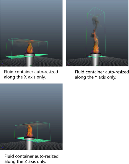
For example, if you want the fluid container to resize only along the Y axis, with the X and Z axis not resizing, do the following:
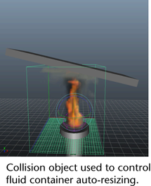
You can create a polygon object, such as a polygon cube, and use it as a collision object for the fluid. Position and scale the polygon object so that the fluid density collides at the location where you want the fluid to stop resizing. Make sure you hide the polygon object when you render the fluid.
Emit speed using a Surface emitter
If you use a collision object to control auto-resized boundaries, the motion of the object has no affect on fluid velocity values. If you want the motion of the object to push the fluid, you can instead emit speed from its surface.
Add a low density volume emitter
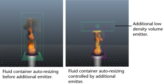
You can control how much a fluid container resizes by adding a low density volume emitter to the fluid container. If you set the density Emission Method of the new volume emitter to Replace, it replaces this portion of the contents with a very low density each frame. Since the replaced density is lower that the Auto Resize Threshold value, the fluid does not expand on the boundary adjacent to that region.
An advantage to this method is that the boundary created by the low density emitter is open, allowing the fluid to flow through.
Add a low density volume emitter by doing the following:
When you play the simulation the fluid does not expand into the volume defined by the second emitter.