Learning Resources > Tutorials > Getting Started with Maya > Polygonal Modeling > Lesson 1: Modeling a polygonal
mesh from a reference image >
Using 2D reference images
You can use front, side, and top views from drawings, sketches, or photographs to help visualize your 3D model in Maya, much like an architect or engineer creates their designs from the plan and elevation views of a blueprint.
You can import 2D images into your orthographic camera views as image planes. An image plane is a 2D object (plane) that places an image file in the scene view. By default, an image plane only appears in the camera to which the image plane is connected. Image planes are also used to create backgrounds and environments when rendering.
When you load an image into an image plane, it appears in your selected orthographic view at the origin along an axis that is perpendicular to the selected orthographic view. You can refer to the image in the orthographic view to define the silhouette and character lines of your model. You can move the image plane, change its transparency, or turn it off.
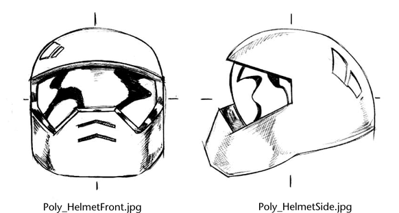
For this lesson you load two images we’ve provided for the lesson into image planes in the front and side orthographic views of your scene. You’ll refer to them frequently while you model the helmet.
To load reference images into the front and side orthographic views
The perspective view is located in the top right corner and the other views show your scene from the top, front, and side.
This image can be found in the GettingStarted directory that you set as your Maya project:
HelmetFront.jpg appears in the front view and depicts a drawing of the helmet.
This image can be found in the GettingStarted project directory:
HelmetSide.jpg appears in the side view.
By referring to the image planes in the orthographic views as you work, you can correlate how a feature in one view, appears in another. While a top view reference image is useful in many cases, it isn’t critical for this lesson.
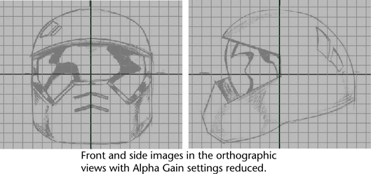
The image planes can be set so they appear partially transparent to allow you to work with the polygonal components more easily. To do this you’ll select the front and side orthographic cameras and modify the transparency of the images.
To modify the transparency of the reference images
The Channel Box displays the keyable attributes for the Front orthographic camera.