


Map UVs onto a subdivision surface
Switch to a level that contains the faces you want to map. For example, if you want to map the entire surface, switch to level 0 so you can select faces across the entire surface.
For whichever level you choose, Maya converts the faces you select down to the finest level and applies the mapping to those faces.
For example, if a face at level 0 has refinements to level 3, the mapping is applied to level 3 faces. If there are no finer levels, the mapping is applied to faces you selected on the current level.
If faces are not selected, no mapping occurs. Maya does not automatically change to the face component mode, as it does when you try to map polygons.
Planar Mapping assigns UVs to the surface by projecting them in a single direction. Where the projection intersects the surface, Maya assigns UVs.
This mapping technique keeps the amount of UV shells low. However, it usually results in UV shells that overlap because the projected UVs strike both sides of the surface. As a result, you’ll probably need to separate the overlapping UVs using Layout UVs.
To map UVs with Planar Mapping
 .
.
To avoid overlaps, Automatic Mapping assigns UVs to the surface by projecting them inward from multiple planes simultaneously. Where the projections intersect the surface, Maya assigns UVs.
To map UVs with Automatic Mapping
.
Although this mapping technique avoids overlapping UVs, it usually creates many small UV shells. As a result, you may want to combine the small UV shells into larger shells, for example, combining shells that correspond to fingers together with the shell corresponding to the palm.
It’s easier to create textures for the model when the UVs of adjacent faces are combined in a logical way. To combine UV shells, you use Edit UVs > Merge UVs and Edit UVs > Sew UV Edges.
To resize or rotate the projection plane
If the manipulator doesn’t appear, select subdPlanarProj in the Channel Box.
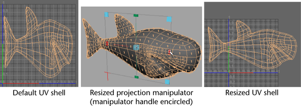
If you map a model of a long fish, the UV shell will be stretched by default to fit in a square (see the following illustration). The stretched shape could result in a texture that looks stretched on the model.
To avoid this problem, you can resize the projection manipulator until the UV shell becomes more oblong, like the long fish model.
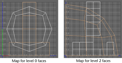
In the figure on the left, level 0 faces were selected to be mapped. The resulting UV shell is round, but there are also lines in the shape of an upside-down T. These other lines correspond to the faces that were selected on level 0. They appear only because those faces are still selected; select elsewhere and they no longer appear.
In the right figure, level 2 faces were selected to be mapped. The resulting UV shell is orange (meaning it’s selected) and is shaped like an arc. There is also a UV shell in the shape of an upside-down T, with a section missing. This UV shell corresponds to the level 1 faces. It still has the default UV arrangement (an upside-down T), because it was not actually mapped; only level 2 faces were mapped.