


oceanShader / ocean (texture)
The Ocean texture can be used to simulate a range of water wave patterns, from small scale waves in a bathtub to large stormy sea swells. It is designed to be used as a displacement map.
Turn off feature based displacement on objects that are assigned the shader before applying as a displacement. This sets up a bump node in addition to the displacement, allowing you to keep the number of triangles low. To see wave motion, animate the Time attribute. This texture is defined internally (procedural) using Perlin noise and sine waves that are driven by the Time attribute.
The Ocean shader simulates the way color changes with light and view angle for an ocean effect.
Use this attribute to animate the Ocean texture. You can keyframe the Time attribute to control the rate and amount of change of the ocean texture in your scene. This value represents seconds for a water surface at the given scale value. Type the expression "= time" into the Time box to create approximately correct animation speed relative to the scale.
Defines how fast waves move. It scales the input time used to determine wave movement.
When Wave Speed is 1.0 Maya creates the correct speeds for open ocean waves at the scale determined by the Maya units and the Scale attribute. For example, if the scale is 10 and the wave speed 1, 1 unit represents 10 meters and the waves will move at the correct speed.
To freeze the waves, make the speed zero.
You cannot change the speed over time using this attribute. You need to change the animation on the Time attribute instead.
Observer Speed cancels out transverse wave motion by moving a simulated observer. This is similar to animating the UV Offset of the texture relative to the wind direction.
When Observer Speed is 1.0 the primary waves do not appear to travel because the viewer is moving at the same speed as the waves. The secondary waves still move relative to the primary ones.
Controls the number of interpolated frequencies between Wave Length Min and Wave Length Max.
If this value is not an integer, then the number of created frequencies is the rounded up value, but the amplitude for the extra frequency is proportional to the remainder (for example, 0.25 for 8.25) This allows this attribute to be smoothly animated.
Defines the variance in wave direction with respect to the wind direction.
If it is zero, then all waves travel in the same direction.
If it is one, then waves travel in random directions.
Inconsistency of the wind direction along with other effects like wave refraction tend to cause a natural variation in wave direction.
Controls the size of waves relative to their wave length.
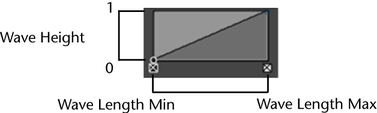
The left edge of the graph represents waves with the shortest wavelengths and the right edge represents waves with the longest wavelengths (as determined by Wave Length Min and Wave Length Max).
If the value is 1.0, then the waves are half as tall as they are long.
If the graph is a horizontal line, then all waves will be exactly the same height proportional to their length. See Set fluid attribute ramps.
Controls the amount of turbulence at different wave frequencies.
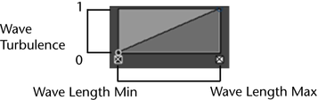
The left edge of the graph represents waves with the shortest wavelengths and the right edge represents waves with the longest wavelengths (as determined by Wave Length Min and Wave Length Max).
For values of 1.0 the wave motion will be completely turbulent at the defined frequency.
For each wave frequency, the turbulence wave component consists of multiple sine waves at that frequency. This is the most computationally expensive attribute. Making it zero will speed up renders significantly, although it is important for simulations of stormy or windy water. The Wave Peaking attribute only affects the turbulent wave layer, so there will be no affect from the Wave Peaking attribute wherever this value is zero.
For details on creating the curve, see Set fluid attribute ramps.
Controls the amount of crest formation for waves across the range of wave frequencies. Wave Peaking simulates a side to side sloshing of waves, as opposed to up-down motion. Wave Turbulence must be non-zero for this attribute to have an effect, as it is only applied to the turbulent waves.
When this attribute is non-zero many more evaluations of the noise function are performed, and thus the computation speed will be affected.
For details on creating the curve, see Set fluid attribute ramps.
Controls how transparent or opaque the material is. Black means completely opaque (the default), and white means completely transparent. You can set it to any level in between. You can also control transparency on a per-channel basis; for example, if you set this to red, then only the red channel will be transparent.
Defines how much a ray of light will bend when it passes through an object. This attribute only works if your material is partially or completely transparent (see “Transparency”), refractions are turned on (see “Refractions”), and you are rendering using Ray Tracing (set in Render Settings).
If the Refractive Index is set to 1.0, then light does not bend when it passes through the object. Here are some other useful values for Refractive Index: air: 1.0, water: 1.33, gasoline: 1.45, crystal: 2.00, glass: 1.5, ice: 1.309, quartz: 1.6, ruby: 1.77, sapphire: 1.77, salt: 1.54, alcohol:1.329, emerald: 1.57, polystyrene: 1.55.
Makes a material appear opalescent, as if it were emitting light itself, such as lava or a phosphorescent moss. A slight touch of incandescence on vegetable matter, for example, can make the vegetation look alive.
By default, the color is black, which has no effect on the surface.
See also Glow.
Ambient Color is black by default, which means it does not affect the material’s over-all color. As the ambient color becomes brighter, it affects the material’s color by lightening it and blending the two colors.
If there are ambient lights in the scene, then the color and brightness of those lights are used to control how much the ambient color contributes to the final color of the material.
Simulates the way light diffusely penetrates through translucent objects. This means that when light shines on one side of the object, the other side is partially illuminated. This can be used for effects such as clouds, fur, hair, marble, jade, wax, paper, leaves, etc.
If Translucence is set to 0 (the default) then no light shows through the object. If it is set to 1, all the light shows through.
Simulates the way light scatters more in a forward direction through translucent objects. Thin objects like a leaf, or low density objects like a cloud tend to scatter more in a forward direction.
When the Translucence Focus is 0.0, translucent light is scattered in all directions. As the focus value is raised the translucent light is scatter more in the light direction. This makes the backlit side of a leaf glow more than the front lit side. At high focus values you will see a halo or glow around the light source when seen through a translucent object.
Use Reflectivity to make an object reflect light like a mirror.
Set this to 0 if you don't want your material to reflect at all. Increase the value to make brighter reflections. Note that brighter reflections hide more of the base surface color. This attribute is only meaningful if there is a reflection map, or if you are Ray Tracing.
Defines a simple sky to ground environmental reflection using a ramp. The left of the ramp is the top of the sky and the right is the bottom. For details, see Environment.
Controls the brightness of the glow (the faint halo of light around the material). Glow Intensity is 0 by default, meaning that no glow is added to the material. As you increase the Glow Intensity, the apparent size of the glow effect increases.
Glow Intensity is different from the Incandescence attribute in two important ways:
The attributes in this section control how this fluid shows up in the matte (alpha channel or mask) when you render with one. This is useful if you will be compositing your rendered images.
Matte Opacity Mode
Select how Maya uses the Matte Opacity value.
The entire matte for the fluid is set to the value of the Matte Opacity attribute. This option is like “Opacity Gain”, except that the normally-calculated matte values are ignored in favor of the Matte Opacity setting. If there are transparent areas on the object, the transparency in these areas is ignored in the matte. Use this setting to composite an object with transparent areas, when you don’t want the background to show through them.
The Matte Opacity value is ignored, and all the matte for this fluid is set to be transparent. Use this option when you use substitute geometry in a scene to stand in for objects in a background image that you will be compositing with later. Your stand-in objects will ‘punch a hole’ in the matte. This allows other computer-generated geometry to pass behind your stand-in objects. Later, when foreground and background are composited, the results will be correct, with the background object showing through the ‘black hole’ areas.
Matte Opacity has a default value of one, so by default Solid Matte and Opacity Gain have no effect.