Create curve flow


To use the Curve Flow effect

  1. Select the curve.
  2. Select Effects > Create Curve Flow > .
  3. Set attributes in the Create Flow Effect Options window (see Edit attributes of the Curve Flow effect), then click Create.

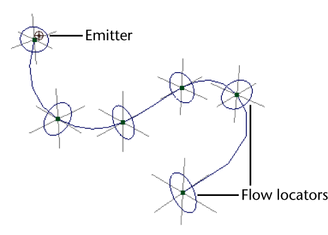
    An emitter and flow locators appear on the curve. The flow locators are visual aids that show the maximum spread of the particles during animation. For details on altering the speed and spread of the particles, see Work with flow locators.

  4. Play the animation.

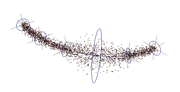
    Emitted particles flow along the curve. You can move the curve or its CVs to change the direction of flow.

  5. Select the emitted particles, and use the Attribute Editor to choose the desired render type, color, opacity, lifespan, and so on.
  6. Render the scene with software or hardware rendering, whichever is appropriate for the render type of the particles.

Edit attributes of the Curve Flow effect

The following attributes appear in the Create Fire Effect Options window when you select Effects > Create Curve Flow > . You can edit many of the attributes with the Attribute Editor after you use the Curve Flow effect. Exceptions are noted in the text.

To display the attributes in the Attribute Editor, first select the Curve Flow node in the Outliner or workspace (see Curve Flow Group Name below). To select the Curve Flow node in the workspace, select the selection handle near the first flow locator.

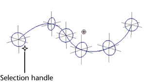
If you use the Curve Flow effect two or more times on the same curve, you’ll see multiple selection handles near the first flow locator.

Work with flow locators

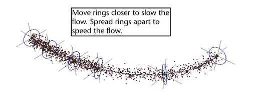
Flow locators control the speed and diameter of the flow in different parts of the curve. You can scale the flow locator rings to expand or shrink the flow diameter in that area. You can move the rings along the curve to speed or slow the flow in that area. This is useful when you’re simulating fluid flow down uneven surfaces. The flow is slower where rings are closer together. The flow is faster where rings are further apart. You can therefore space the rings to adjust the flow speed.

To expand or shrink flow diameter at part of a curve

  1. Select the Curve Flow node.
  2. Select the flow locator ring without selecting the curve.
  3. Select the Scale tool and drag the yellow scale icon to scale the ring along all three axes.

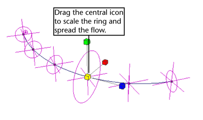
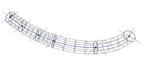
    You cannot scale along a single axis. Emission always occurs in a circular region. The ring represents the outer boundary of emission at that point. Maya interpolates the emission diameter between neighboring rings. In other words, the emission diameter increases or decreases smoothly between neighboring rings of different diameters.

    An example follows:

To speed or slow flow at an area of a curve

  1. Select the Curve Flow node.
  2. In the Extra Attributes section of the Attribute Editor, edit the value of the desired locator. The locators are listed in the Attribute Editor in the order of their position on the curve. To move the locator, do one of the following:
    • Try different numbers for a locator until you see it move to the desired position.
    • Click the locator name in the Channel Box then slowly middle-drag the mouse back and forth in the workspace until you see the locator move to the desired position.

To enhance icon display

  1. Select the Curve Flow node.
  2. In the Extra Attributes section of the Attribute Editor, set these attributes:
    Display Subsegments

    When on, displays a marker at each control subsegment for better visual representation of their locations. You can’t change their location directly. You can do so indirectly by moving the flow locators.

    Display All Circles

    Displays circles for the control subsegments. This simply makes it easier to see the subsegments.

    Display Thickness

    Displays circles for control segments and subsegments. Also shows a wireframe that represents the cylindrical region of flow. This gives you a more detailed view of the region of flow.