To
create a surface flow
- Select one or more NURBS surfaces.
- Choose
Effects > Create Surface Flow >
 .
.
- Set controls in the option window as
needed.
For controls related
to creation, see
Set surface flow creation controls.
For controls that you
can edit later, see
Editing a surface flow.
- Click Create in
the Create Surface Flow Effect Options window.
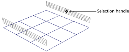
An emitter and flow manipulators
appear on the surface.
NoteIt may take a long
time to create a surface flow. Creation time is affected by the
number of objects in the scene, by the number of other flows already
existing, and by the number of flow manipulators you specify.
- Play the animation.
- Render the scene with software or hardware
rendering, whichever is appropriate for the render type of the particles.
Set surface flow creation
controls
The creation controls
apply only at the time of creation. You cannot modify these controls
later.
Editing a surface flow
You
can edit these attributes after you create the Surface Flow effect
by selecting the surface flow selection handle and opening the Channel
Box or the Attribute Editor, Extra
Attributes section.
NoteYou cannot directly
rotate or translate manipulators, because they automatically adjust
to any changes in the shape of the surface. However, you can edit
the Location attributes to move
them along the surface.
- Display Sub Manips
-
Turns visibility on or off for the flow sub manipulators.
- Show True Manip Shape
-
By default, the manipulators
are displayed as smooth bands that wrap around the base surface in
exactly the shape that you specify. The actual shape
that the effect uses depends on the Manipulator Resolution value
that you set at the time you created the surface flow.
To see that shape, turn
on the Show True Manip Shape attribute.
This does not affect the way that the surface flow moves the particles.
It simply lets you see how accurate the simulation is trying to
be.
- Smooth Sub Manips
-
You can use this option to smooth the transition of
sub manipulators between flow manipulators that are spread apart
or moved together. If you haven’t changed the location of flow manipulators,
this option has no effect, because the default positions are smooth
already.
- Display Min Loft, Display
Max Loft, Display Edge Loft
-
When Visibility is
turned on (in the Display section of the SurfaceFlow Attribute
Editor), you can choose to display the flow loft’s inner
edge, outer edge, or the distance of the edge by turning on Display
Min Loft, Display Max Loft, and Display
Edge Loft respectively.
- Emitter Rate
-
Sets the degree of particle emission in the flow. The
emission is applied to the surface area of the first flow manipulator.
An emission rate of 0 (zero) means no particles appear.
- Random Speed
-
Sets the amount of random changes in the particle
speed. Use this attribute to create a more natural effect.
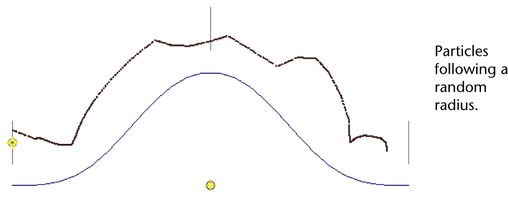
- Random Radius
-
Sets the amount of random changes in the particle
emission radius, so that particles spread beyond the flow manipulator
loft. Use this attribute to create a more natural effect.
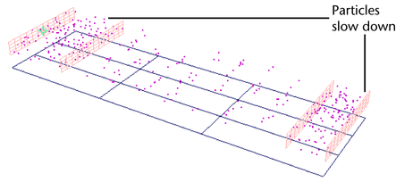
- U or V Location
-
Controls
the position of each flow manipulator, measured in U or V. You can
move manipulators anywhere along the surface in any order.
Typically, you adjust
the manipulator locations to affect the particle speed. Particles
slow down between manipulators that are close and speed up between
manipulators that are distant.
You may also need to
adjust the location of a manipulator if it is placed at the end
of converging threads. For example, a manipulator at the end of
a cone would be invisible because the surface at that point is zero.
These values are always
between 0 and 1, regardless of the parameterization of the original
surface. Therefore, a value of 0.5 will be approximately in the
center of the surface.
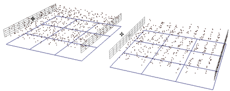
- Min U or V, Max
U or V
-
Controls
the beginning and end positions of each flow manipulator, measured
in U or V. Adjust these values if you want the flow to cover only
part of the surface. For example, you can break up a surface into
two adjacent flows by ending one flow (Max setting) at the same
point where the second flow begins (Min setting).
These values are always
between 0 and 1, regardless of the parameterization of the original
surface. Therefore, a value of 0.5 will be approximately in the
center of the surface.
- Min Distance, Max Distance
-
Controls
the distance between the surface and the top and bottom of each
flow manipulator. By adjusting these values, you can affect not only
the proximity to the surface, but also the thickness of the flow.
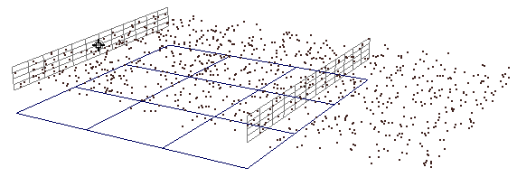
- Min Age Ratio, Max
Age Ratio
-
Specifies
what part of the total particle lifespan occurs in the flow—a
ratio of flow lifespan to total lifespan. For example, if you set
the Max Age Ratio to 0.5, the particles
flow along the surface for half their lifespan and then continue beyond
the last flow manipulator.
The age ratio also indirectly
affects particle speed. In the above example, the particles only have
half their lifespan to reach the end of the flow, so they speed
up.
- Goal Weight
-
Sets
how much all particles in the flow are attracted to the flow manipulators.
Values can range from 0 (no weight) to 1 (full weight).
Edit particle lifespan
To edit the particle
lifespan, you must select the particle node, not the flow group
node, because there may be several particles per flow.
- Particle Lifespan
-
Sets when all particles
in the flow die. This option controls the total lifespan, but the Min and Max
Age Ratio control the lifespan within the flow. As a
result, Particle Lifespan may affect the
particle speed in order to meet the requirements of the Min and Max
Age Ratio settings.
Connect flows on separate
surfaces
You can connect flows from
separate surfaces so they share the same particles. The workflow
is different depending on whether you create flows at the same time
or start with an existing flow.
To create connected flows
- Select the surfaces in the order you
want the particles to flow.
- Choose
Effects > Create Surface Flow > .
- In the options window, turn off Create
Particles Per Flow.
- In the Control Resolution option,
specify the number of flow manipulators per surface.
- Click Create.
The effect creates one
flow per surface, with the particles flowing in the order of selection.
NoteBy default, the Min and Max
Age Ratio settings are evenly divided among the flows.
As a result, a gap appears if the surfaces are separated. Edit the Min and Max
Age Ratio settings if you want the particles to fill
the gap.
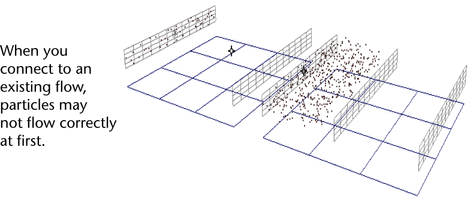
To connect an existing flow
- Select the particle from the existing
flow, along with the surfaces or flows you want to connect. (The
selection order doesn’t matter.)
- Choose
Effects > Create Surface Flow.
There will be one flow
per surface, but the particles may not flow correctly. Correct the
flow of particles using the following steps.
- For all flows after the starting flow,
change the Emitter Rate to 0 (zero).
- In all the flows, adjust the Min and Max
Age Ratio settings so the particle life span extends
evenly among all flows.
The following table gives
example settings for two flows.
| Flow |
Min Age Ratio |
Max Age Ratio |
A
|
0
|
.5
|
B
|
.5 or higher
|
1
|
Delete flows
Because surface flows create expressions
in the affiliated particle objects, you should not delete flows
using the  key
or
Edit > Delete option. Follow
the instructions below.
key
or
Edit > Delete option. Follow
the instructions below.
- Select the flow or flows you want to
delete.
- Choose
Effects > Delete Surface Flow > .
- Edit the Delete Surface Flow
Effect Options as needed.
- Click Delete.
Resolve incorrect deletion
If you accidentally delete
a flow with the key
or
Edit > Delete option,
follow these instructions to clean up the nodes in your scene.
- Delete the particles associated with
the flow.
- Remove the shaders for the particles
by opening the HyperShade or Hypergraph and
choosing Delete Unused.