For more information, see Help > Node and Attribute Reference.
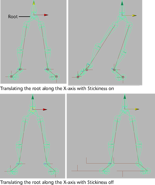
When this attribute is on and the current IK handle has no keyframes, the current IK handle will stick to its current position when you pose the skeleton with another IK handle or by translating, rotating, or scaling the joints directly. When this attribute is on and there are keyframes on the current handle, Stickiness is ignored. Default is off.
You can use Stickiness when posing a joint chain with an IK handle to prevent unwanted joint chain movement. For example, you can turn on Stickiness for the IK handles of a model’s legs if you want the feet to stay firmly planted on the floor while you move and pose the hips of the model.
Specifies the priority of the current IK handle. Priority is useful only when a joint chain has more than one IK handle. The purpose of Priority is to ensure that the IK handles of a joint chain solve in the correct order so that they properly produce the desired animation.
When you set Priority for the IK handles of a joint chain, Maya calculates the priority for each handle based on its position in the hierarchy. The IK handle with a Priority of 1 has first priority, and will rotate the joints first. An IK handle with a Priority of 2 has second priority, and will rotate the joints next, and so on. Default is 1.

Sets the weight value for the current IK handle.
The weight value, in conjunction with the current distance between the IK handle’s end effector and its goal, serve to prioritize the solutions of the current IK chain and those of its other IK handles that have the same Priority settings. See Priority.
When the end effector of two or more IK handles with the same Priority cannot reach their goals simultaneously, the IK handle whose end effectors are furthest from their goals and whose weights are greatest are solved first.
Not available for ikSCsolver, ikRPsolver, or ik2Bsolver handles.
Specifies whether the current IK handle’s end effector favors reaching its goal’s orientation or position.
When this attribute is set to 1, the end effector tries to reach the IK handle’s position. When this attribute is set to 0, the end effector only tries to reach the IK handle’s orientation. A value of 0.5 specifies that the end effector equally favors reaching both the position and orientation as closely as possible. Default is 1.000.
An Ik Blend value of 0.000 sets the animation mode to pure FK, and an Ik Blend value of 1.000 sets the animation mode to pure IK. When the Ik Blend value is a number between 0.000 and 1.000, then the animation on the current skeleton is blended IK and FK. See IK/FK blending.
Lets you manipulate and key the joints of a joint chain that has an animated IK handle. In addition to being located in the local IK Handle Attributes, Ik Fk Control is also present in the global skeleton settings ( Skeleton > Enable IK/FK Control).
IK Solver
Specifies the type of solver for the IK handle. See IK solvers. The default options are the following:
Specifies the position of the pole vector’s end point.
Pole vector is only applicable to IK handle’s that use the rotate plane solver. See Rotate Plane solver.
 . See
also
IK Spline Handle Tool.
. See
also
IK Spline Handle Tool.
Not available for single chain IK handles.
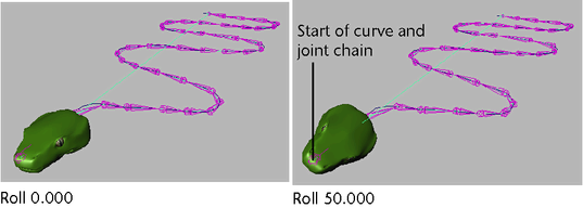
Twists the joint chain from the end joint by the specified amount.
You can also control the rotation of the joint chain by manipulating the twist disc. See Pose joints with spline IK curves.
Twist Type
This attribute is only available for spline IK handles.
This option specifies how the twist occurs in the joint chain:
Add Advanced Twist Control Attributes
This button reveals additional attributes for the current Spline IK handle.
World Up Type
Specifies the type of up vector constraint that is applied to the joints in the Spline IK handle’s joint chain.
Sets the Up vector of the first and last joints as the direction from the joints to the center of the specified start and end objects.
Type the names of the start and end joint up objects in the World Up Object and World Up Object 2 fields. The results from the start and end of the chain are interpolated along the chain to provide up vectors for the middle joints.
Sets a particular vector in the local space of the specified object as the Up vector for all joints.
Type the local vectors in the Up Vector fields and the object name in the World Up Object field. The default Up Vector value is (0,1,0). This means that the object’s positive Y axis is used as the Up Vector.
Sets a particular vector in the local space of the specified objects as the Up vector for the start and end joints in the current chain.
Type the local vectors and object name for the start joint in the Up Vector and World Up Object fields, and type the local vectors and object name for the end joint in the Up Vector 2 and World Up Object 2 fields. The results from the start and end of the chain are interpolated along the chain to provide up vectors for the middle joints.
Sets specific vectors in worldspace as the up vectors for the start and end joints.
Type the start joint worldspace up vectors in the Up Vector fields and the end joint worldspace up vectors in the Up Vector 2 fields. The results from the start and end of the chain are interpolated along the chain to provide up vectors for the middle joints.
Specifies which local joint axis is aligned with the worldspace up vector. Positive Y axis is the default.
If you select any of the Closest axes, either the positive or negative axis is used at each joint, depending on which is currently closer to the worldspace up vector. The Closest option lets you preserve the orientation of joint chains whose axes flip every few joints.
When the World Up Type is Object Rotation Up or Object Rotation Up (Start/End), the values in these fields specify vectors in the local space of the specified up objects.
When the World Up Type is Vector or Vector (Start/End), the values in these fields specify worldspace world vectors.
The Up Vector fields are for the start joints, and the Up Vector 2 fields are for the end joints.
When the World Up Type is Object Up, Object (Start/End), Object Rotation Up, or Object Rotation Up (Start/End), the name in this field specifies the object to use for computing the up vector. The name in this field connects the worldspace matrix of the transform with the IK handle.
The World Up Object field is for the start joint, and the World Up Object 2 field is for the end joint.
Twist Value Type
Sets how the additional, user-defined twist is distributed along the joint chain.
Connects a texture to the Twist Ramp attribute to provide explicit twist values for the entire chain. Twist is measured in degrees.
Each joint is assigned a UV texture coordinate of (0,j/N), where j is the joint index in the chain and N is the number of joints in the chain. The alpha value returned by the texture is multiplied by the value of the Twist Ramp Multiplier attribute to produce the twist for each joint.
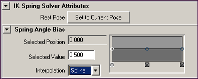
Rest Pose
The rest pose sets the basic appearance of a spring IK joint chain. The rest pose also determines how angle biases are calculated across a spring IK joint chain.
By default, the rest pose is the pose (orientation and position of joints) of the spring IK joint chain at the time of its IK handle’s creation.
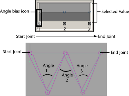
Specifies the bias value for the selected angle bias icon. The angle bias is a relative weight that determines how fast a joint rotates in relation to the other joints in the same chain. The angle bias functions as a multiplier, influencing the angles between the bones in the target joint chain.
For example, if the Selected Value of the first angle in the joint chain is 1, and the second angle in the chain has a Selected Value of 0, then the first angle moves twice as fast as the second angle.
This attribute is inherited from the ramp node and it has no effect on the spring IK solver.
For example, for a spring IK joint chain with five joints, three icons appear on the Spring Angle Bias ramp. The first icon along the ramp’s horizontal axis represents the Selected Value for the target angle nearest to the spring IK joint chain’s start joint.