User Guide > Modeling > Polygonal Modeling > Combining, separating,
and splitting > Split polygon components >
Insert an edge loop
The Insert Edge Loop Tool lets you select and then split the polygon faces across either a full or partial edge ring on a polygonal mesh.
The Insert Edge Loop Tool is useful when you want to add detail across a large area of a polygon mesh or when you want to insert edges along a user-defined path.
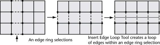
For a description of an edge ring, please refer to Select an edge ring.
When you insert an edge loop, you are splitting the polygon faces associated with the selected edge ring. The Insert Edge Loop Tool lets you insert one or more edge loops across a full, partial, or multidirectional edge ring.
Possible workflow scenarios are as follows:
To insert an edge loop across a full edge ring on a polygonal mesh
 .
.
When Maintain position is set to Relative distance from edge, the preview locator is positioned based on a percentage distance along the edge (25%, 50% and so on) When Auto complete is turned on you can select a full edge ring and immediately split the corresponding faces.
A green dotted edge loop preview locator line appears within the edge ring that is selected perpendicular to the edge you clicked. The edge loop preview locator indicates where the new edge loop will be inserted across the mesh once you release the mouse button.
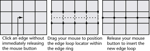
The new edge loop is inserted on the polygon faces associated with the selected edge ring. The new edge loop remains selected so that you can perform additional operations on the edges.
For example, selecting the Move Tool to move the selected edge loop, selecting Edit Mesh > Extrude to extrude the selected edge loop, or converting the edge loop selection to faces.
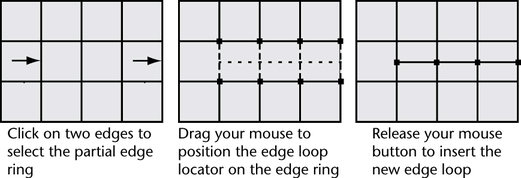
To insert a partial edge loop across a polygonal mesh
.
The edge is selected and a green vertex appears on the edge you clicked to indicate the selection.
All of the edges between the first and second edges you clicked become selected and a dotted green edge loop preview locator appears across the selected edge ring. The preview locator indicates where the new edge loop will be inserted across the mesh.
 +
+  on that
edge and continue your selection. If you want to cancel the edge
selection entirely, click anywhere in the scene view off of the mesh.
on that
edge and continue your selection. If you want to cancel the edge
selection entirely, click anywhere in the scene view off of the mesh.
 or
or  and
select Complete Tool from the marking
menu that appears.
and
select Complete Tool from the marking
menu that appears.
An edge loop is inserted at the location that was indicated by the edge loop locator on the polygonal mesh. The new edge loop remains selected so that you can perform additional operations on it.
For example, selecting the Move Tool to move the selected edge loop, selecting Edit Mesh > Extrude to extrude the selected edge loop, or converting the edge loop selection to faces.
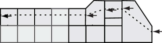
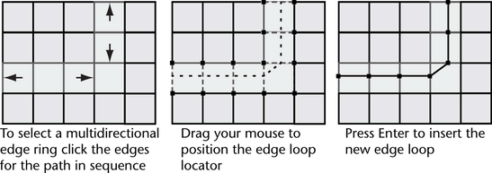
To insert a multidirectional edge loop
.
The edge is selected and a green vertex appears on the edge you clicked to indicate the selection.
All of the edges between the first and second edges you clicked become selected and a dotted green edge loop preview locator appears across the selected edge. The preview locator indicates where the new edge loop will be inserted across the mesh.
+ on the
desired edge. If you want to cancel the edge selection entirely,
click anywhere in the scene view off of the mesh.
or and
select Complete Tool from the marking
menu.
An edge loop is inserted at the location that was indicated by the preview locator on the polygonal mesh. The new edge loop remains selected so that you can perform additional operations on it.
For example, selecting the Move Tool to move the selected edge loop, selecting Edit Mesh > Extrude to extrude the selected edge loop, or converting the edge loop selection to faces.
You can turn many of the Insert Edge Loop Tool options on or off while the tool is active using a marking menu. This assists your workflow by letting you continue your work without having to re-open the tool options window.
To change the tool options when the Insert Edge Loop Tool is active
+  + anywhere
within the scene view away from a surface.
+ anywhere
within the scene view away from a surface.
The Insert Edge Loop Tool options (Auto Complete, Absolute distance from edge, Relative distance from edge, and Multiple edge loops) appear on a marking menu.
You can continue to use the Insert Edge Loop Tool and the options you selected will be used.