Layering
The key concept for combining hardware with software rendering
is layering. It refers to building a final image from multiple
sub-render passes. The concept is already common in pure hardware
rendering: a surface might be too complex to be rendered in one
pass, so a first render pass may lay down the base color, another
adds glossy, glow, or fur effects, and a final pass puts highlights
on top. Each layer accumulates color in the frame buffer. Newer
hardware also permits combining successive layers in ways other
than accumulation of the frame buffer by providing a feedback path
from the previous layer result to the current layer
calculation.
In this document, the term Layering is extended to also cover
pre-rendering of shadow maps and and other maps as listed above.
Although the result is stored as textures and not accumulated in
the image frame buffer, the feedback paths in recent hardware
designs are beginning to blur this distinction.
Layering does not necessarily involve rendering the entire
scene. It is more common to group sections of the scene by object
or by material. Many objects contain multiple materials, and it is
fairly expensive to switch materials in the graphics hardware
because that may involve reloading of textures, lights, shaders,
transformation matrices, and other context information. Reloading
is far slower than rendering triangles. For this reason,
object sections are normally sorted by material, in addition to
normal depth sorting to avoid sending objects that are hidden
behind others at all.
Effectively, hardware rendering is a fairly long sequence of
rendering separate object portions, many of them multiple times,
each time resulting in some form of pixel rectangle. The rendering
operations form a dependency graph, with pixel rectangles flowing
along the edges of the graph:
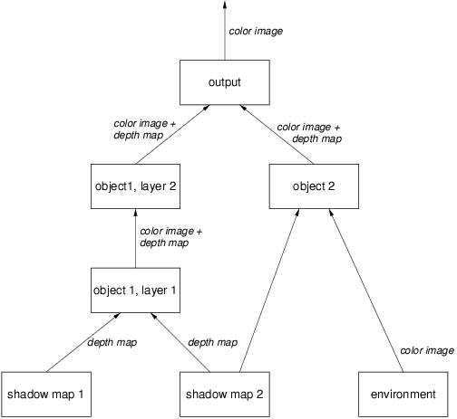
Rendering begins at the bottom of the graph because all inputs
to a node must be available before beginning to calculate the node.
Object 1 consists of two layers, one computing illumination (and
hence needing to know which points are in shadow) and the other
adding some extra information such as glows. Object 2 is only a
single pass illuminated only by one light, but using a chrome
reflection model that requires an environment map. Both objects are
combined to calculate the final output image. In practice, such
graphs are far larger than this trivial example.
The design goal of hardware support in mental ray 3.3 is that
some of the graph nodes are computed in software, and others in
hardware. For example, to add global illumination to the above
graph, a software node would compute the global illumination map
(using final gathering or photon mapping), then another software
node would create a light map to
bake the indirect light into a texture, which is then used by a
hardware node to add to the direct light contribution computed by
hardware shading:
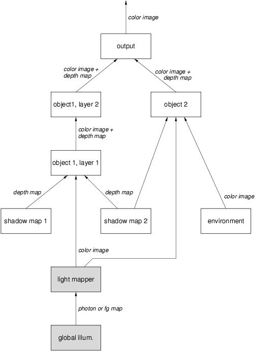
The shaded nodes are software nodes; the unshaded nodes are
hardware nodes. Note that it is often possible, as in the case of
global illumination maps, to compute the map once and re-use it for
multiple frames.
Copyright © 1986-2007 by mental images GmbH