Top 10 Tips on Using FEA within AIP Simulation Suite
- Try to avoid applying loads on points or small edges as these will cause non convergence of results due to very high localized stresses.
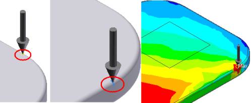
- Try to avoid applying constraints on points or small edges as these will cause non convergence of results due to very high localized stresses.
- There are 3 elements used within AIP including Brick, Tetrahedon (Tet) and Shells.
- Brick elements require fewer elements than Tetrahedon elements to get accurate results. Note Brick elements are only used by the software for simple shape components
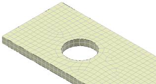
- Tetrahedons are the default elements as they have the ability to mesh more complicated components
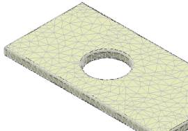
Note: By simply adding fillets the mesher uses Tetrahedons instead of Brick Elements.
- Shell elements are more accurate than both Brick and Tet elements for thin components like Sheet metal parts.
Note Using shell element will speed up the analysis time when compared to using Solid Tetrahedon elements.
- The deformation results are not affected by using a finer mesh or lower mesh relevance.
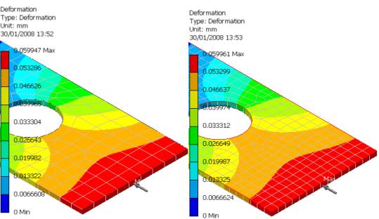
Note: The analysis calculation will be quicker using a lower mesh relevance.
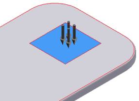
- You can use the Spit feature command to define the precise location and size of a face to which you can apply a load or constraint. This method is better than creating dummy features, to which loads can be applied, as it avoids potential high localized stresses.
- If you have an assembly made of the same material you can use the derived feature command to convert the assembly to a single component. This will then allow you analyse your component.
- This method will not allow you to determine the contact stresses between components.
- Make sure you fill any gaps between components, to avoid any mesh errors.
- Results below a Factor of Safety of 1 are not valid. So always make sure the Factor of Safety plot shows all values above 1.
- Always suppress Design Features that are not part of the structural integrity of the component. This will also help to speed up your analysis time and avoid possible mesh errors, in addition to high localized stress problems.
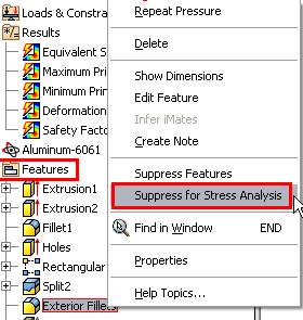
Note: Its easier to suppress features within the stress analysis environment
-
Deformation values should always be small in relation to the overall size of the component. If you expect larger deformations then you need to conduct a non-linear analysis.
- Use frictional constraints to model
Quarter models.
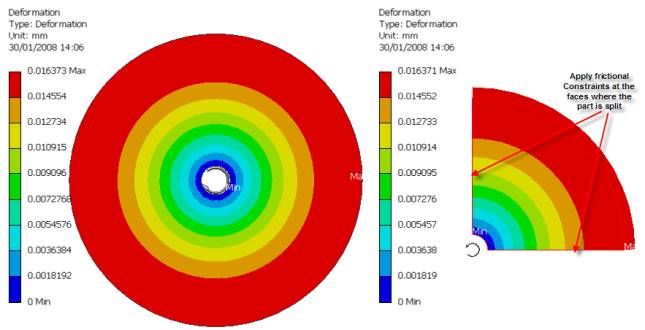
Note: A quarter model will achieve
the same results, with using fewer elements.
|
|
For further tips & tutorials visit
www.vdssolutions.co.uk
wasim@vdssolutions.co.uk
Wasim YounisVDS Solutions Ltd