The Edit UVWs dialog contains a number of rollouts that provide various tools for editing texture coordinates. Among these are tools for transforming and subdividing UVWs procedurally, thus providing artists with useful shortcuts for more-efficient texture editing.
The Edit UVWs dialog rollouts are arrayed vertically on the right side of the dialog, and can be opened, closed, and scrolled just like rollouts on the command panels.
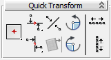
You can transform UVW sub-objects manually with the tools on the upper toolbar, or procedurally with these tools.

 Set Pivot
 Align Horizontal
  Align Horizontal to PivotLines up selected sub-objects horizontally and moves them vertically to the pivot position.
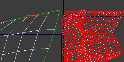
 Align Horizontal in PlaceLines up each set of connected, selected texture vertices and edges (not polygons) horizontally and moves them to the average
of their vertical positions.
Align Horizontal in PlaceLines up each set of connected, selected texture vertices and edges (not polygons) horizontally and moves them to the average
of their vertical positions.
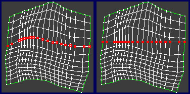
Left: Initial vertex selection; Right: after Align Horizontal
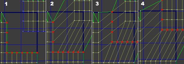
At the Edge level, if you press Shift when clicking the button, Align loops through all selected edges and lines up all the edge loops of those edges horizontally. In that case it is enough to select one edge on each edge loop to line up. It can also line up UV seam edge loops.
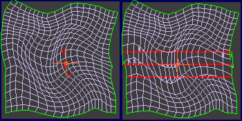
Left: Initial edge selection; Right: after Align Horizontal In Place with Shift held down
 Align Vertical
 Align Vertical to Pivot Lines up selected sub-objects and moves them horizontally to the pivot position.
 Align Vertical in Place Lines up each set of connected, selected vertices and edges (not polygons) vertically and moves them to the average of their
horizontal positions.
Align Vertical in Place Lines up each set of connected, selected vertices and edges (not polygons) vertically and moves them to the average of their
horizontal positions.
At the Edge level, if you press Shift when clicking the button, Align loops through all selected edges and lines up all the edge loops of those edges vertically. In that case it is enough to select one edge on each edge loop to line up. It will also line up UV seam edge loops.
 Linear Align
  Align to Edge
 Rotate -90 around Pivot
 Rotate 90 around Pivot
 Space Horizontally
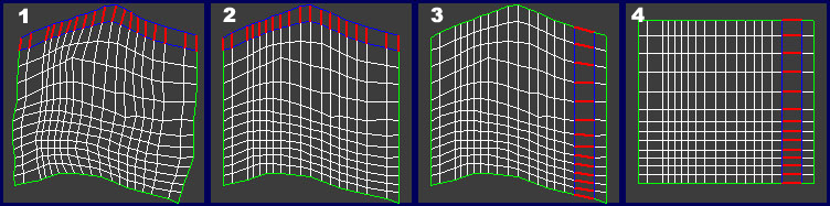
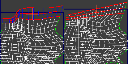
For example, to create a horizontal loop of texture polygons of uniform width, first select the horizontal edge loops above and below the polygons, then click Space Horizontally.
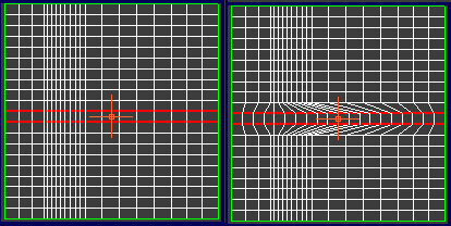
Left: Initial edge-loop selection
Right: After using Space Horizontally; the vertices within each loop are spaced evenly.
Space Horizontally is best used at the Edge level. It also works at the Vertex level, but it converts the vertex selection internally to edges. Thus, to avoid ambiguous results when working at the Vertex level, use it with single loops of selected vertices.
At the Edge level, if you press Shift when clicking the button, Space Horizontally works on the edge loop to which each selected edge belongs. In that case it is enough to select one edge on each edge loop to space. It also applies to UV seam edge loops.
 Space Vertically
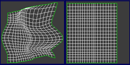
For example, to create a vertical loop of texture polygons of uniform height, first select the vertical edge loops on the polygons' left and right sides, then click Space Vertically.
Space Vertically is best used at the Edge level. It also works at the Vertex level, but it converts the vertex selection internally to edges. Thus, to avoid ambiguous results when working at the Vertex level, use it with single loops of selected vertices.
At the Edge level, if you press Shift when clicking the button, Space Vertically works on the edge loop to which each selected edge belongs. In that case it is enough to select one edge on each edge loop to space. It also applies to UV seam edge loops.
 Straighten Selection
  Relax Until Flat
Relaxing texture vertices can make them more evenly spaced, resulting in easier texture mapping.
 Relax: Custom
 Relax Settings
Most UV vertices and edges on cluster seams (that is, on the outer edge of a cluster) have shared sub-objects on other cluster seams. Both represent the same sub-object in the object mesh, but are represented twice or more
in the UV mapping because of the subdivision into clusters. Use the Stitch tools to connect selected sub-objects on a cluster
seam to their shared sub-objects on another cluster's seam. To see shared sub-objects in the editor window (highlighted in
blue by default), turn on Display menu  Show Shared Sub-Objects, or Unwrap Options dialog Show Shared Subs. You can also use the Show Shared Subs setting to change the color of highlighted shared sub-objects. Also, with Show Vertex Connections on at the Vertex level, you can see exactly which vertices will be connected to which.
Although Stitch works only at the vertex and edge levels, it is available at all sub-object levels, and applies to all seam-based vertices and edges associated with the selected sub-objects. If only one UV vertex is selected and it has more than one corresponding UV vertex, it will be stitched to the closest one. In all other cases Stitch finds the best match, if the match is unselected, or stitches to the selected match.
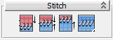
 Stitch to Target
 Stitch to Average
 Stitch to Source
 Stitch: Custom
This tool is also available as Stitch Selected on the editor Tools menu.
 Stitch Settings
Use the tools in the first row of this rollout for breaking up texture coordinates into separate clusters. The Flatten tools work on selected texture polygons, or if no polygons are selected, on all polygons.
 Break
Break Flatten by Face Angle
  Flatten by Smoothing Group
When flattening by smoothing group, in order to form a separate cluster, a group of polygons must be fully enclosed by hard edges; that is, polygons that do not share any smoothing group IDs with their neighbors. If some polygons have multiple smoothing group IDs, it's possible that the texture coordinates would not be able to be split into separate clusters.
 Flatten by Material ID
 Flatten: Custom
 Flatten Settings (on Flatten: Custom flyout)
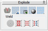
With the exception of Target Weld, the Weld commands here combine edges on different clusters at the average of their positions.
 Target Weld
Turn on Target Weld, and then drag one vertex to another vertex, or one edge to another edge. As you drag, the cursor changes in appearance to cross hairs when it's over a valid sub-object. While this command is active, you can continue welding sub-objects, and change the sub-object level. To exit Target Weld mode, right-click in the editor window.
 Weld Selected Subobject Misc. Preferences group.
 Weld All Selected Seams
  Weld Any Match with Selected
The Peel tools provide an implementation of the LSCM (Least Square Conformal Maps) method of unwrapping texture coordinates, for an easy and inutuitive workflow in flattening complex surfaces. This rollout also includes tools for working with the Pin aspect of the Peel feature. When using Peel, pinned vertices are held in place while the rest of the vertices move.
For a brief demonstration of how to use the Peel tools, see this procedure.
 Quick Peel
Quick Peel is suitable for simple texture-mapping applications, but for better control, use Peel Mode instead (see following).
 Peel Mode
While Peel Mode is active, you can create seams with the Edit Seams and Point-to-Point Seams tools and they automatically "peel" off as you go. Alternatively, in the editor, select some edges and use the Break tool to split the edges and automatically re-peel the cluster.
When Auto-Pin Moved Vertices is on (the default), moving a sub-object in Peel mode pins (locks) all vertices belonging to the sub-object.
 Reset Peel
Use Reset Peel to reconnect map seams on previously mapped geometry, or to quickly break off and Peel a selection.
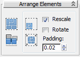
Use these tools to arrange elements automatically in various ways. Packing is useful for adjusting the layout so that clusters don't overlap.
The Pack tools apply only to selected clusters when one or more sub-objects are selected, or to all clusters when nothing is selected.
 Pack: Custom
Pack: Custom respects the Rescale Priority value (see following) when Rescale Clusters is on.
 Pack Settings (from Pack: Custom drop-down)
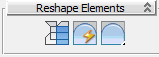
 Rescale Elements
Rescale Elements respects the Rescale Priority value (see following) whether or not the Rescale switch is on. When groups are present, it always applies to the group members plus any selection (or all clusters if nothing is selected). If no groups are present, Rescale Elements applies only to selected clusters when one or more sub-objects are selected, or to all clusters when nothing is selected.
 Pack Together
Pack Together respects the Rescale Priority value (see following) when groups are present and the Rescale switch is on.
 Pack Normalize
Pack Normalize respects the Rescale Priority value (see following) when groups are present and the Rescale switch is on.
Grouping in the Unwrap UVW modifier lets you specify that certain texture clusters should stay together during Pack operations (see preceding). You can also specify relative rescaling for grouped clusters.
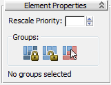
Rescale Priority applies to these tools under the specified conditions:
To use Rescale Priority, first group one or more clusters (see Group Selected, following), then set the value. Then, when you use an operation that involves rescaling, the Rescale Priority value is applied to this group as a multiplier.
For example, say you group some clusters, and then select a polygon belonging to one of the clusters and set Rescale Priority to 0.5. Then you apply Pack Together or Pack Normalize to all clusters, with the Rescale option enabled. The result is that the clusters belonging to the group are half the size that they would be otherwise. (Non-grouped clusters always use a scaling factor of 1.0, or 100%.)
The Groups functions are available at the Polygon sub-object level only. Using Pack Together or Pack Normalize on grouped clusters retains the original spatial relationship of the members of each group, and optionally applies scaling based on the Rescale Priority value for a group and the state of the Rescale option.
For example, if two or more clusters are superimposed because they represent different parts of the geometry that use the same part of the texture map, you could keep them from separating during Pack procedures by selecting them all and then clicking Group Selected.
 Group Selected
After you create a group, you can, in effect, select the group by selecting any polygon in the group. Doing so enables two features:
 Ungroup Selected
 Select Group
If you use Select Group with multiple groups (that is, multiple polygons selected in different groups), only one group is selected. Which group gets selected is unpredictable.


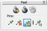
 Pin Selected
 Unpin Selected
 Auto-Pin Moved Vertices
 Select Pinned Verts