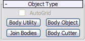
Available on the Create panel drop-down list of object types is the Body Objects entry. When you choose this item, the Object Type rollout contains four buttons for different features of the SAT plug-in, described in this topic.
For an explanation of the Body Objects format, see the introductory topic of this section: SAT Files.
Enables setting attributes for multiple Body Objects simultaneously, particularly the display and render resolutions. To use, select several Body Objects, then click Body Utility. This opens the Operator Parameters, Rendering Approximation, Viewport Display Settings, and Face Display Parameters rollouts on the Create panel.
When you change a setting on any of these rollouts, the new value is applied to all selected Body Objects.
Converts a single selected object to Body Object format. To edit this object, use the Body Object rollouts on the Modify panel, described in the sections that follow.
Converts multiple objects, typically Body Objects and 3ds Max primitives, to operands of a special type of Body Object called Join Bodies. This format enables automatic welding of edges as well as the Boolean operations Intersect and Union. To use, select two or more objects and click Join Bodies.
You can then adjust how the objects are joined on the Conversion Parameters rollout, and access the operands on the Operator Parameters rollout. You can also transform the operands at the Operand sub-object level on the modifier stack.
Additional rollouts available for Join Bodies objects are Rendering Approximation, Viewport Display Settings, and Face Display Parameters.
The Body Cutter tools let you perform Boolean “cutting” operations such as Subtract on Body Objects, much the same way that the ProCutter compound object works in 3ds Max. For details, see Body Cutter Parameters Rollout.
Additional controls for Body Cutter objects are the same as for Join Bodies (see preceding).
When you import an SAT file or convert an object in 3ds Max to Body Object format and then select it, the first rollout on the Modify panel is Editable Body Object. These controls allow you to perform available operations at the various sub-object levels, including flipping faces, welding and exploding (un-welding) edges, and more.
The Object Parameters rollout controls let you combine and separate Body Objects while maintaining the solid-geometry format. Also available here are commands for subdividing objects, splitting faces, and performing simple Boolean operations. For example, you can position a spline curve over an object and then use the curve to cut through the entire object or selected faces in the view direction, thus subdividing the faces.
Body Objects created with Join Bodies or Body Cutter are compound objects and thus contain multiple operands. The commands on this rollout enable you to modify the display, ordering, and selection of the operands. You can also use these features to remove operands and to make copies or instances of operands.
A Body Object is defined procedurally, and so must be converted to a mesh object for rendering. These controls determine how the software performs this conversion. The default method is to generate a new mesh for rendering that depends on the view. Alternatively, rendering can use the viewport mesh generated by the viewport mesh settings. The default settings work well for creating the render mesh in most situations.
A Body Object is defined procedurally, and so must be converted to a mesh object for displaying in the viewport. These controls determine how the software performs this conversion. You can specify a different conversion method for rendering or use the Viewport Display settings.
Use these settings to define material and mapping properties such as ID, offset, and tiling for selected faces.


 Create panel