This topic describes controls that are common to point surfaces, CV surfaces, and the various dependent surface types. A rollout labeled Surface Common contains the surface sub-object controls for NURBS surfaces. Another rollout, Material Properties, controls mapping on surface sub-objects, and is described in its own topic. See Surface Approximation for a description of that rollout. The final rollout for surface sub-objects depends on the type of surface selected.
To transform surface sub-objects:
 select one or more surface sub-objects.
The sub-object selection tools are the same as for other kinds of sub-objects. In addition, you can use the H key when the Keyboard Shortcut Override toggle is on. See Sub-Object Selection.
The Selection group box, described under "Interface" later in this topic, provides additional options for selecting surfaces.
 (Select And Move) or another transform and then drag in a viewport to transform the selection.
The shape of the model changes as you interactively transform the surfaces.
To use the keyboard to select surface sub-objects:
You can select surface sub-objects using the Ctrl key and the arrow keys. The arrows traverse the sub-objects in the order they were created. To do so, follow these steps:
 (Keyboard Shortcut Override Toggle).
 ( Surface) sub-object level, set the selection controls to select surfaces individually.
Click or drag to select surfaces.
( Surface) sub-object level, set the selection controls to select surfaces individually.
Click or drag to select surfaces.
At the Surface sub-object level, the left and right arrow keys move forward and backward through individual surfaces in the order they were created. The up and down arrows are equivalent to left and right.
You can also use the H keyboard shortcut (while the Keyboard Shortcut Override Toggle is on) to display a dialog and select surfaces by name. Ctrl+H displays only the names of surfaces directly beneath the mouse cursor.
Select the surface and then click Make Loft. 3ds Max opens a Make Loft dialog. 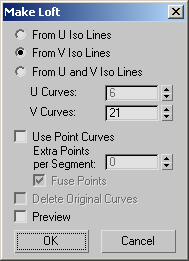
One or two blue curves appear on the surface to indicate where the break will occur.
You cannot break a trimmed surface.
The surface extension is invalid and disappears if it would cause the surface to intersect itself or if the edge of the surface touches itself but is not closed. For example, you can't extend the top of a cylinder.
The surface that owns the highlighted edge is highlighted in yellow, to help you distinguish which edge you are choosing when two surfaces have coincident edges.
The Join Surfaces dialog is displayed, which gives you a choice of methods for how to join the surfaces. Whichever method you choose, 3ds Max creates a single surface that replaces the two original surfaces.
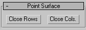
Select the surface sub-object and then click Close Rows or Close Cols.
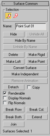
Surface sub-object rollout
The controls on this rollout apply to all surface types. Depending on the type of surface, an additional rollout is displayed with controls specific to that type of surface.
The selection buttons for surface sub-objects let you select either individual surfaces, or surfaces that are connected in space.
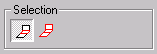
Surface sub-object selection controls
Single Surface All Connected Surfaces
Shows the name of the currently selected surface. It is disabled if you have selected multiple surfaces.
By default, the name is the name of the surface type ("CV Surface," "Point Surface," "Blend Surface," and so on) followed by a sequence number. You can use this field to give the surface a name that you choose.
Makes the surface rigid. The only editing allowed on a rigid surface is to transform it at the Surface sub-object level. You can't move a rigid surface's points or CVs, or change the number of points or CVs.
Rigid surfaces reduce the amount of memory used by the NURBS model. Making surfaces rigid improves performance, especially for large and complex models.
When a surface is rigid, you can't see its points or CVs when you are at the Point or Surface CV sub-object levels. If the model has no nonrigid surfaces and no point curves, the Point and Surface CV sub-object levels aren't available at all.
To make a surface no longer rigid, click Make Point or Make Independent. Editing the surface with Break, Join, and so on also makes it no longer rigid.
Displays a Make Loft dialog to convert the surface sub-object to a (dependent) U loft or UV loft surface. Can also change the dimension used to construct a U loft surface.
You can’t use Make Loft if the surface sub-object is in an error condition.
Displays a Make Point dialog to convert any kind of surface to a point surface. You can also use Make Point to change the number of rows and columns if the surface is already a point surface.
Click to display the Convert Surface dialog. This dialog provides a general way to convert a surface to a different type of surface. You can convert between lofts, point ("fit") surfaces, and CV surfaces. The dialog also lets you adjust a number of other surface parameters.
Detaches the selected surface sub-object from the NURBS model, making it a new top-level NURBS surface object. The Detach dialog is displayed, which lets you name the new surface. The new object is no longer part of the original NURBS model.
To create a new top-level NURBS surface that is a copy of the selected surface, turn on Copy before you click Detach.
When on, the normal for each selected surface is displayed. There is one normal per surface sub-object. The normal is displayed at the surface's UV origin, so displaying normals can help you see how materials will be mapped. On the other hand, the normal can be hard to see if you are zoomed out. Default=off.
Turn on to reverse the direction of the surface normals. Default=off.
Joins two surface sub-objects together. After you have joined the surfaces in a viewport, the Join Surfaces dialog is displayed. This dialog lets you choose the method for joining the two surfaces. You can join only original edges of surfaces; you cannot join edges created by trimming.
This additional rollout is displayed when a CV surface is selected.

Let you set the degree of the surface in either the U or V dimension. The higher the degree value, the greater the continuity. The lower the degree, the more discontinuous the surface segments become. The degree can't be less than one or greater than the number allowed by the number of CVs in the specified dimension. Degree 3 is adequate to represent continuous surfaces, and is stable and well behaved. Default=3.
Setting the degree greater than 3 isn't recommended because higher-degrees are slower to calculate and less stable numerically. Higher-degrees are supported primarily to be compatible with models created using other surface modeling programs.
The number of CVs in a given dimension must be at least one greater than that dimension's degree.
Automatic Reparameterization group
The controls in this group box let you specify automatic reparameterization. They are similar to the controls in the Reparameterize dialog, with the addition that all choices except for None tell 3ds Max to reparameterize the curve automatically; that is, whenever you edit it by moving CVs, refining, and so on.
Chooses the chord-length algorithm for reparameterization.
Chord-length reparameterization spaces knots (in parameter space) based on the square root of the length of each curve segment.
A uniform knot vector has the advantage that the curve or surface changes only locally when you edit it. With chord-length parameterization, moving any CV can potentially change the entire surface.
The close controls let you close a surface. They are displayed on the CV Surface rollout while an independent CV surface sub-object is selected. They are disabled if the surface is already closed in that direction.
Displays the Rebuild CV Surface dialog, which lets you specify how to rebuild the surface. Rebuilding the surface can change its appearance.
Displays the Reparameterize dialog. Reparameterizing a surface changes the surface's parameter space to provide a better relation between control point locations and the shape of the surface.

 Modify panel
 Expand the NURBS object's hierarchy.
  The Lock Selection Set button is useful when you transform NURBS sub-objects. You can make a selection in one viewport, click
Lock Selection Set (or press the
The Lock Selection Set button is useful when you transform NURBS sub-objects. You can make a selection in one viewport, click
Lock Selection Set (or press the