


This rollout controls material mapping onto a NURBS surface sub-object.
To apply a mapped material to a surface sub-object:
 Material Editor to assign a mapped material to the surface.
To use multiple map channels on a single surface sub-object (example):
Now when you assign a mapped material, maps on map channel 1 use the default UV tiling, while maps on map channel 2 use the channel 2 tiling. An easy way to see this is to create a checker map on channel 1, and make one checker color another checker map on channel 2.
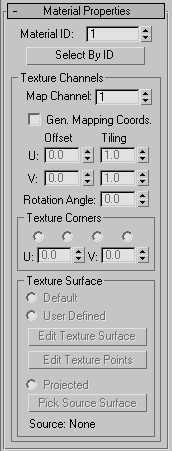
Use this to change the surface’s material ID number. Multiple material IDs in a single NURBS object let you assign a multi/sub-object material to the NURBS object.
Displays a Select by Material ID dialog.
The controls in this group box support materials, including tiling and positioning mapping coordinates on the surface.
Chooses a UV coordinates map channel. Range=1 to 99. A single surface can use up to 99 texture channels. Default=1.
The controls in this group box let you explicitly set which texture surface UV values to use at the corners of a surface. These controls are especially useful when you are matching the textures of adjacent surfaces.
These controls are disabled unless Generate Mapping Coordinates is on.
Unavailable unless you've chosen one of the Corners radio buttons. When available, you use these spinners to set the U and V texture values for the chosen corner.
By default, the U and V values for most surfaces range from 0.0 to 1.0. For some kinds of geometry converted to a NURBS surface, these ranges can vary.
The controls in this group box let you choose a method for mapping texture to the currently selected NURBS surface sub-object, and to adjust the parameters for some of the chosen methods.
These controls are available when Generate Mapping Coordinates is on.
A texture surface is a surface associated with the surface sub-object. The texture surface controls how materials are mapped. In effect, changing the texture surface stretches or otherwise changes the UV coordinates for the surface, altering the mapping.
Maps can shift with certain surface approximation methods. This effect is especially noticeable when the surface has animated CVs. You can reduce or eliminate map shifting by changing the mapping method to User Defined.
Click to display the Edit Texture Surface dialog, which lets you control UV mapping on this surface. This button is available when you've chosen User Defined as the texture surface method.
Click to edit texture surface points directly in viewports. This button available when you've chosen User Defined as the texture surface method.
While Edit Texture Points is on, the points of the texture surface are displayed in viewports, where you can adjust their positions by using the selection and transform tools.
Generates the texture surface by projecting the texture of another NURBS surface sub-object in the NURBS model. The projection travels along the direction of the normals of the source surface.
Projected texture surfaces are relational: if you update the source surface, the texture updates on all the surfaces it projects onto.
If you use the same source surface to project a texture onto several other connected surfaces, the textures will match along the boundaries where the mapped surfaces touch.

 Modify panel