Command entry:
Select a Body Object or a Join Bodies or Body Cutter object.


Modify panel
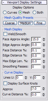
Viewport Display Settings rollout
A Body Object is defined procedurally, and so must be converted to a mesh object for displaying in the viewport. These controls
determine how the software performs this conversion. You can specify a different conversion method for rendering or use the
Viewport Display settings.
Interface
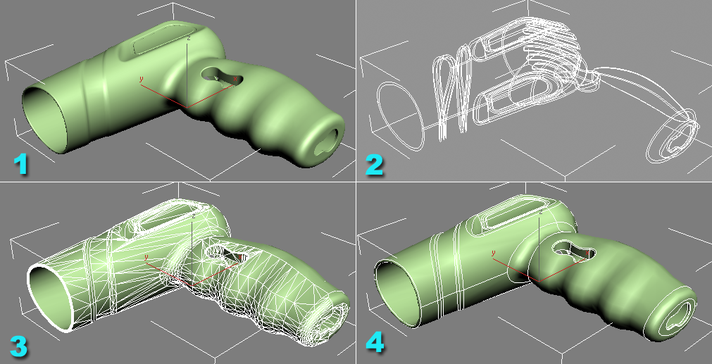
- Display Options
-
Choose how the Body Object displays in the viewports:
- Displays only the isoparametric curves in both shaded and wireframe viewports.
- Displays only the polygons for both shaded and wireframe viewports.
- Displays the mesh in shaded viewports and edges and isoparametric curves in wireframe viewports. If you activate the Edged
Faces option in a shaded viewport you can also see the curves in this mode.
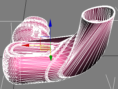
- Mesh Quality Presets
-
Choose an overall setting that automatically determines the remainder of the Viewport Display settings. The default choice,
Coarse, provides adequate viewport rendering quality with maximum speed of interaction.
- Lowest-quality mesh generation; generates the fewest polygons.
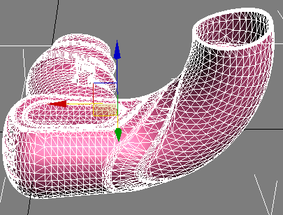
- Medium-quality mesh generation.
- Highest-quality mesh generation; generates the largest number of polygons.
Mesh Display group
The Mesh Display settings control how the Body Object is displayed in the viewport. These settings are also used when converting
to editable mesh/poly format to control how the polygons are created.
- Weld/Smooth
-
Smoothes out polygons, removing tiny edges and polygons.
This option welds vertices and uses smoothing groups instead of the natural surface normals. This is useful primarily when
preparing the viewport mesh for conversion to an editable mesh where welding is needed. If you don't use this option, duplicate
vertices will result between some of the faces of the output mesh corresponding to the edge boundaries between faces of the
body object.
- Face Approx Angle
-
The maximum angle for each pair of polygon faces. Faces with an angle greater than this value between them are subdivided
into multiple polygons. Decreasing this value increases the mesh resolution.
- Edge Approx Angle
-
Similar to Face Approx Angle, but defines the maximum angle for a polygon edge. The default value of 0.0 disables this setting.
- Face Distance %
-
The maximum allowable absolute error between the mesh and the actual precise (solid) geometry. The percentage is based on
the size of the object. Adjusting this value is the preferable way to increase the mesh quality without getting too many polygons.
- Edge Distance %
-
Similar to Face Distance %, but defines the maximum allowable error for polygon edges. The default value of 0.0 disables this
setting.
- Max Edge Len. %
-
The maximum length for any mesh edge. Adjust this setting to get a mesh without long, narrow polygons. This value is used
to control the subdivision of the display mesh. The default value of 0.0 disables this setting.
TipWhen using a modifier to deform the Body Mesh, set Max Edge Len. % to 2.0 or 3.0 to obtain smooth deformation.
- Smoothing Passes
-
The number of passes during the smoothing step. Increasing this value can help improve the shape of very narrow triangles.
Curve Display group
- Lines U/V
-
The number of crosshatch curves for isoparametric curve display; the number of subdivisions in the U or V direction.
NoteThe additional curves produced by settings above 0 (the default) are for display purposes only, and have no effect on the
geometry. For an illustration, see
Edge.
- Display Surface Knots
-
Displays isoparametric curves at the NURBS knots on the faces.
- Approx Angle
-
The angle tolerance to use in the display of isoparametric curves. For finer curves, use lower values. For a circle, if you
set this to 10, you get 36 or more segments.
TipThis is the primary setting for controlling the quality of the curve display, and will suffice in most situations. For shallow
curves, try using Curve Distance % (see following) as well.
- Curve Distance %
-
The chord height used to display isoparametric curves. For finer curves, use lower values. For example, setting this to 1%
with a high Angle Tolerance value gives you about 16 segments on a circle.
TipThis setting is most useful with shallow curves, such as a car hood, where the whole angle across the curve is only a few
degrees.