Components | Clusters | Attributes | Transforms | Playback Info
Controls the visibility of various types of elements and attributes in the 3D camera views. Applies to different views depending on how it is displayed:
To set options for all open geometry views at once: Choose View  Visibility Options (All Cameras) from the main menu.
To set options for a specific view: Choose Visibility Options from the Show menu (eye icon).
For additional information, see Displaying Types of Elements and Other Data.
| Curves |
Displays curve objects. |
| NURBS Surfaces |
Displays NURBS surface objects. |
| Polygon Meshes |
Displays polygon mesh objects. |
| Implicit Geometry |
Displays implicit objects. |
| Nulls |
Displays nulls. |
| Lights |
Displays lights. |
| Cameras |
Displays cameras. |
| Point Clouds |
Displays point clouds (ICE particles). |
| Hair |
Displays hair objects. |
| Instances |
Displays model instances. |
| Annotation Objects |
Displays annotation objects. |
| Environment |
Uses the current pass' Environment shader for background and reflections in High Quality display mode. |
The checkboxes in the left column affect the display of selected objects, and the right column affect unselected objects.
Information is shown only for selected objects.
Displays various attributes of the objects in a scene. These can be useful when you are working on specific aspects of particular elements. However, displaying too many attributes can clutter the display and slow down interaction. The checkboxes in the left column affect the display of selected objects, and the right column affect unselected objects.
Some of these attributes may be obscured unless the display mode is Wireframe or Bounding Box. With other display modes, you can activate Use XRay Shading on the Display Options tab of the Options.
| Name |
Displays the names of objects. |
| Attachments |
Displays whether objects have annotations or synoptic properties: |
| User Keywords |
Displays key word applied with Set User Keyword(s) in the context menu of a 3D view, explorer, or schematic. |
| Relations |
Displays dotted lines between objects, showing expression, constraint, link, modeling, and other relations. If you select a constrained object, a white link is shown between it and the object to which it is constrained. If you select a constraining object, a light purple link is displayed between it and the object that is constrained to it. |
| Relation Info |
Displays text labels indicating the type of relation between objects. For some types of relation, additional information may also be displayed. |
| Animation Cues |
Colored triangles that provide information about an object's animated transformations, and let you open the animation editor or select an action clip. |
| Cones |
Displays outlines representing the area covered by spotlights and the camera frustum (see Displaying the Camera Cones (Frustum) [Cameras and Motion Blur]). |
| Collision Primitives |
Displays a yellow wireframe around a rigid body when you set the Collision Type geometry in its Rigid Body property editor to a bounding box, sphere, or capsule. This wireframe shows the extents of its volume for collision calculations. |
| PolyMesh Boundaries |
On polygon meshes, displays boundary edges (unshared edges that belong to only one polygon) in light blue and hard edges (edges with discontinuous shading) in dark blue. |
| PolyMesh Hulls |
Displays the control hull of subdivision surfaces that have been created using the Subdivisions options on the Polygon Mesh tab of the Geometry Approximation Property Editor. |
| PolyMesh Internal Edges |
Displays the edges of the triangles that result after quads and n-gons are tessellated. The internal edges appear as dotted lines (sparse dotted lines on invisible polygons when they are displayed). |
| Subdivision Surface |
Displays the subdivided result of subdivision surfaces of that have been created using the Subdivisions options on the Polygon Mesh tab of the Geometry Approximation Property Editor. |
| NURBS Boundaries |
On NURBS curves and surfaces, displays minimum U knots or knot curves in red and minimum V knots or knot curves in green. |
| NURBS Hulls |
Displays dark blue line connecting the control points of NURBS curves and surfaces. |
| Chain Critical Zone |
Displays the critical zone as a pair of cones around the root of a kinematic chain. If the chain effector enters the critical zone, the chain may flip. The critical zone is blue when the default preferred axis of rotation is used or when a preferred axis constraint is applied to the chain. The critical zone is green when an up-vector constraint is applied to the chain. |
| Chain Joint Rotation Limits |
Displays the circles at the joints, the joint's rotation limits, and the stiffness of kinematic joints. For 2D joints, the rotation limits are indicated by a red circle with two lines. The space opened between the lines indicates the range of motion for the joint. For 3D joints, there are three circles in red, green, and blue for the X, Y, and Z axes, respectively. The stiffness is indicated by filling in the joint. The degree to which the joint is filled in represents the degree of stiffness. |
| Distance to Output Camera |
Displays the distance in Softimage units of objects from the output camera. |
| Point Cloud Points Only |
Overrides the default particle display modes and shape type and displays all particles as points. You may want to use this for faster performance or for a less cluttered display when you're not tweaking the particles. You can also set this in the point cloud's Particle Display property editor — see Setting the Particle Display. |
| Point Cloud Trails |
Displays lines giving a visual cue to the particle's velocity. The amount of trail left by a particle depends on its speed of emission. You can also create a custom particle display attribute to do this (using Point Velocity), giving you more display options — see Creating Particle Display Attributes. |
| Point IDs |
Displays each particle's ID under it. The ID gives you information on particle age and distribution — see About Particle IDs and Indices. You can also create a custom particle display attribute to do this, giving you more display options — see Creating Particle Display Attributes. |
| Hair Interpolation Group IDs |
Displays the ID of the interpolation group next to the root of each guide curve of a hair object. You can create interpolation groups using Split or Shatter on the Hair panel. If guide curves have been merged, their interpolation guide IDs are shown with an asterisk. |
| Locked Hair Points |
Displays a little blue padlock icon next to locked points on hair objects. You can lock and unlock points using the corresponding commands on the Hair panel. |
| Property Maps |
Displays weight, envelope weight, and symmetry maps. This option has an effect only in Constant or Shaded mode. Constant mode shows the maps more clearly than Shaded. |
| Display/ICE Attributes |
Toggles the display of:
|
| XRay Surface |
Displays objects whose Opacity is less than 1.0 in their Display properties. |
| Stereo Zero Parallax Plane |
Displays the zero parallax planes for the left and right cameras in a stereo camera rig — see Stereoscopic (3D) Camera Rigs for more information. You can set the zero parallax planes' color and transparency values on the Components tab in the Scene Colors Property Editor. |
| Points Weight |
Displays points in colors that indicate how they are weighted to different deformers, in the case of envelope and spine deformations. |
| Cluster Reference Frame |
Displays a small axes icon showing the averaged center of the selected components or clusters. This reference frame is computed dynamically. You can display this reference frame as a visual guide, which is useful when setting tangency and normal parameters for object to cluster constraints. Note that the displayed cluster reference frame is not necessarily the same as the reference frame use for manipulating components in Local mode. The displayed cluster reference frame is a single average, while non-adjacent component use their own reference frames for manipulation. To enable multiple visual cues when transforming non-adjacent components, turn on Display Multiple Transformation Axes in your Transform preferences. |
| Cluster Reference Frame Info |
Displays the global XYZ position of the averaged center of the selected components or clusters. |
The checkboxes in the left column affect the display of selected objects, and the right column affect unselected objects.
| Centers |
Displays object centers as thin XYZ axes indicators with a white circle at the origin. |
| Centers of mass |
Displays the rigid body's center of mass as a blue box with a yellow axis. The center of mass is the location at which a rigid body object spins around itself when dynamics are applied (forces and/or collisions). By default, the center of mass is defined at the same location as the object's center (wherever the center is located). |
| Object Pivots |
Displays the pivots of objects. Object pivots are the center of transformation when playing back animated rotation and scaling. They appear as thin XYZ axes indicators with a white circle and a black bull's-eye at the origin. When an object's pivot has been deactivated in its Local Transform Property Editor, the center pivot is displayed with desaturated colors. |
Controls the display of the visual cues in viewports, as well as snapping to the grid and reference planes.
Lets you transfer settings to and from the Transform Options property editor.
| Scene/Selection Info | Custom Info | Viewport Slate | Viewport Slate
Controls the display of playback, selection, and custom information in the viewport. You can also enable and define a viewport slate.
| Show Frame Rate |
Displays the scene's frame rate in the middle of the bottom edge of the viewport. |
| Show Vertical Sync (v-sync) Status in Frame Rate |
Displays "sync on" or "sync off", depending on your display driver v-sync settings, when Show Frame Rate is on. This option is available on Windows systems only and does not work with all graphics cards and drivers. If the sync state displayed in the viewport does not match the preference set in Display Preferences [Preference Reference], then the preference is being overridden by the driver. In your driver's settings, you should set v-sync to "application controlled" (or equivalent). If your graphics card does not support this feature, then no sync information will be shown. You should assume that v-sync is enabled. Disabling v-sync can greatly improve playback speed, but can result in minor visual artifacts if the frame changes during a screen redraw. See Troubleshooting Viewing Problems [Viewing and Playback]. |
| Show Current Time |
Displays the current frame in the lower right-hand corner of the viewport. |
| Show Fast Playback Cache Size |
When the Fast Playback Cache is enabled, its size is displayed in the middle of the bottom edge of the viewport. |
You can display custom information in 3D views by specifying preset tokens and text strings to create a viewport slate. A
viewport slate can be defined for a specific camera (choose Visibility Options from the "eye icon" menu), or for all cameras at once (choose View Visibility Options (All Cameras) from the main menu).
You can display a viewport slate for the User, Top, Front, Right, and Spotlight viewpoints, but unlike "real" cameras, viewpoints cannot be used for final rendering. For details, see Cameras and Viewpoints [Viewing and Playback].
You can also copy the contents of any viewport slate to and from the render slate defined for the current pass. For more information about creating a render slate, see the Slate tab in the Render Pass Property Editor.
| Enable |
Enables the display of template information in any viewport set to that particular camera or viewpoint. |
| Copy from Pass Slate |
Copies to this viewport slate the contents of the render slate defined for the current pass. |
| Copy to Pass Slate |
Copies the contents of this viewport slate to the render slate defined for the current pass. |
| Tokens |
Opens a help topic listing all available tokens. For details, see Tokens and Templates. |
| [templates] |
Enter tokens and text strings to create a viewport slate. You can enter template information on a single line or on multiple lines (each line is considered a separate template). The viewport slate recognizes all universal tokens and their optional parameters, as well as the context-specific viewport slate tokens. For information about the available tokens and how to build templates, see Tokens and Templates. |
| Viewport Slate Example |
This viewport slate displays basic camera information, including the values for the near and far clipping planes of a camera named Main_Camera. The template is defined in one line as follows: [Camera] [CameraProjection] near:[Value main_camera.camera.near] far:[Value main_camera.camera.far] 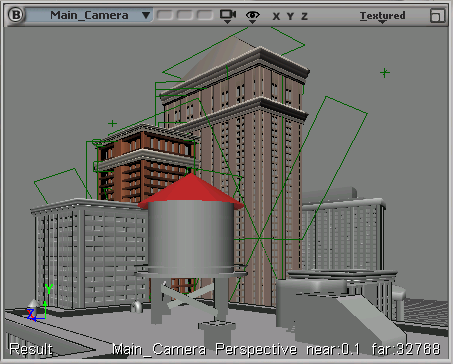
|


