There are a variety of tools and operators for adding points, edges, and polygons to polygon mesh objects. They are all available
from the Modify  Poly. Mesh menu on the Model toolbar, as well as from the context menu that appears when you Alt+right-click (Ctrl+Alt+right-click on
Linux) on a polygon mesh in a 3D view or right-click when polygon mesh components are selected.
Poly. Mesh menu on the Model toolbar, as well as from the context menu that appears when you Alt+right-click (Ctrl+Alt+right-click on
Linux) on a polygon mesh in a 3D view or right-click when polygon mesh components are selected.
Adding and Editing Polygons (Drawing)
The Add/Edit Polygon tool is a multi-purpose tool that lets you draw polygons interactively by placing vertices. You can use it to add polygons to an existing mesh, add or remove points on existing polygons, or to create a new polygon mesh object. There are two preferences that control how the Add/Edit Polygon tool works: Preserve Planarity While Creating Polygons and Action When Connecting CW vs CCW Polygons.
Choose Modify Poly. Mesh Add/Edit Polygon Tool from the Model toolbar or press N.
Click in a 3D view to add a point. If necessary, you can adjust the position by moving the mouse pointer before releasing the button.
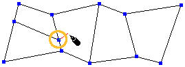
Click an existing point on another polygon in the same mesh to attach the current polygon to it.
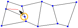
Click an existing edge of another polygon in the same mesh to attach the current polygon to it.
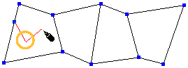
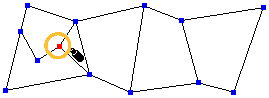
Left-click and drag on a vertex of the current polygon to move it.
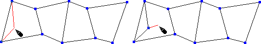
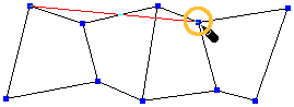
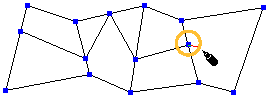
As you move the mouse pointer, the edges that would be created are outlined in red. To insert the new point between a different pair of vertices of the current polygon, first move the mouse across the edge connecting them.
The direction of the normals is determined by the direction in which you draw the vertices. If the vertices are drawn in a counterclockwise direction, the normals face toward the camera and if drawn clockwise, they face away from the camera. As you draw, red arrows indicate the order of the vertices.
When you connect two polygons whose normals point in opposite directions, the behavior is determined by the Action When Connecting CW vs CCW Polygons preference as described in the next section.
If desired, you can activate snapping while using this tool. For more about snapping, see Snapping.
When you have finished drawing a polygon, do one of the following:
To start a new polygon and automatically share an edge with the current one, first move the mouse pointer across the desired edge and then click the middle mouse button. Repeat step 3 as necessary.
To start a new polygon without sharing automatically sharing an edge, click the right mouse button. Repeat step 3 as necessary.
When you are finished drawing polygons, exit the Add/Edit Polygon tool by clicking the right mouse button twice in a row, by choosing a different tool, or by pressing Esc.
Preferences that Affect Drawing Polygons
There are two preferences you can set to control how the Add/Edit Polygon tool works: Preserve Planarity While Creating Polygons and Action When Connecting CW vs CCW Polygons.
To access these options, choose File Preferences from the main menu, then expand Tools and click Polygon.
Preserve Planarity While Creating Polygons
The Preserve Planarity While Creating Polygons preference automatically adjusts the position to preserve the planarity of the polygon when you click to add a new vertex using the Add/Edit Polygon tool. As a result, new vertices may not be added exactly where you click — even if snapping is on.
If this option is off, then it is possible to draw non-planar polygons, for example, by drawing three vertices in the Front view and then a fourth in the Side view.
You can temporarily change the current behavior by pressing Shift while adding points. Pressing Shift allows you to force planarity as you draw a specific polygon when the preference is off, or allow a non-planar polygon when the preference is on.
For more information about polygons and planarity, see Planar and Non-planar Polygons.
Action When Connecting CW vs CCW Polygons
When you draw polygons and connect them to others, the normals might be facing in opposite directions. This occurs if the vertices on two polygons are ordered differently, that is, clockwise versus counterclockwise. When two such polygons are about to be connected, the Action When Connecting CW vs CCW Polygons preference controls what happens:
Prompt user before proceeding: You are prompted to invert polygons or not in each case.
Invert conflicting polygon(s) (and all their adjacent ones): The other polygons are inverted to fit with the current polygon you are drawing. The inversion ripples through adjacent polygons (if appropriate).
Accept CW-CCW connection (with double-edge side-effect): No changes are made to the normal directions. Adjacent polygons with opposite normals are connected by a double edge to preserve the integrity of the mesh structure.
For more information about polygon normals, see Polygon Shading.
You can use the Add Edge tool to split or cut polygons interactively by drawing new edges that connect existing edges or vertices.
Choose Modify Poly. Mesh Add Edge Tool from the Model toolbar or press \.
To specify the starting point for a new edge, do one of the following:
To start drawing an edge from an existing point, click on it.
To start drawing from an existing edge, click on the desired location along the edge. A new point is created.
To start drawing from the midpoint of an edge, press Ctrl while clicking anywhere on that edge. A point is created, evenly bisecting the edge.
To start drawing from a point in the interior of a polygon, press Alt while clicking inside the polygon. A point is added and a triangle is created by automatically adding edges connecting that point to the endpoints of the nearest edge.
To specify the endpoint of the new edge, do one of the following:
If you want the next edge to start from the endpoint of the edge you are currently drawing, click on another point or edge. A new edge is added connecting the two locations. You can use the Ctrl, Shift, or Ctrl+Shift keys while clicking to modify how the new edge is attached to an existing edge as described later in this step. You can repeat this step to draw a strip of edges.
If you want the next edge to share the same starting point as the edge you are currently drawing, middle-click on a point or edge instead of left-clicking. Again, you can use the Ctrl, Shift, or Ctrl+Shift keys while middle-clicking to modify how the new edge is attached to an existing edge as described later in this step. You can repeat this step to quickly draw fans of polygons.
Middle-click to continue drawing edges from the previous point.
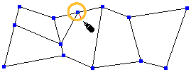
Click in the interior of a polygon to add a point. You can repeat this step to add as many interior points as you like, creating a polyline, before terminating it. You terminate the polyline by attaching the endpoint to an existing edge or point of the polygon, using the left or middle mouse button as described above.
Click inside a polygon to add an interior point.
If you exit the Add Edge tool or start over at a new location (as described in step 5) before you attach the end of the polyline, the interior points are discarded because they do not form a valid mesh structure.
If you use snapping to align the interior points with the grid or other elements, the plane in which the interior points are created depends on the Preserve Planarity During Creation setting in your Polygon preferences. When that preference is on, then the new points snap in screen space but are still created in the plane of the existing polygon.
When that preference is off, the interior points are created at the exact position of the snapping target in 3D space. If you don't use snapping, interior points are always created in the plane of the existing polygon.
For more information about snapping in general, see Snapping. For more information about the Polygon preferences, see Preferences that Affect Drawing Polygons.
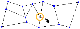
When adding interior points, you can press Alt while clicking to automatically create a triangle by connecting the new point to the endpoints of the closest edge, just as when specifying the starting point in the previous step.
Alt+click inside a polygon to add a point and connect it to the nearest edge by a triangle.
No matter which options you use to draw edges, you can press Ctrl+Z one or more times to undo the last actions without exiting the Add Edge tool. You can also press Ctrl+Y to redo any action you undid.
If you are trying to attach a new edge to an existing edge or vertex, and the target does not become highlighted when you move the pointer over it, it means that you cannot attach the new edge at that location because it would create an invalid mesh.
You cannot attach the edge to this point.
If you draw an edge between two points that already share an edge, no new edge is created — the second point simply becomes the starting point for the next edge you draw. If you click on an edge that is adjacent to the current point, a new vertex is created.
When you are attaching a new edge to an existing edge, you can use the Ctrl, Shift, and Ctrl+Shift keys as follows:
Press Ctrl while clicking or middle-clicking an edge to bisect it evenly.
Press Shift while clicking or middle-clicking an edge to ensure that the angle between the new edge and the target edge snaps to multiples of the Snap Increments - Rotate value set in your Transform preferences. For example, if Snap Increments - Rotate is 15, then the new edge will snap at 15 degrees, 30 degrees, 45 degrees, and so on. Angles are calculated in screen space. For more information about snapping increments, see Incremental Snapping.
Press Shift to attach at multiples of the rotation increment. In this case, the increment is 15 and the edge is attached at 45 degrees.
Press Ctrl+Shift while clicking or middle-clicking an edge to attach the new edge at a right angle to the target edge. The angle is calculated in object space.
When you have finished drawing a strip or fan of edges, do one of the following:
The Add Vertex tool combines some of the capabilities of Split Edge and Move Point.
Choose Modify Poly. Mesh Add Vertex Tool from the Model toolbar or press Insert.
To add and move a vertex, click at the desired location along an edge and then drag the resulting point.
The three mouse buttons let you drag in different ways, depending on the current Transform mode.
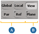
Translation Modes: XYZ modes (A) and Drag modes (B).
If desired, you can activate snapping while using this tool. For more information, see Snapping [Working in 3D Space].
To exit the Add Vertex tool, press Esc or choose another tool.
Welding merges two or more vertices on a polygon mesh into a single vertex.
You can weld pairs of points interactively while using the Weld Point tool.
You can weld multiple selected points either to targets or to their average position using a menu command.
As an alternative to welding large numbers of points, you can filter points by distance (see Filtering Points).
The Tweak Component tool supports welding interactively. See Using the Tweak Component Tool.
The Move Point tool also supports welding interactively with the Alt key. See Using the Move Point Tool.
You can weld points only if they belong to the same polygon mesh object.
|
|
To weld two points interactively using the Weld Points tool
Click and drag a point. As you move the mouse pointer, the point snaps to points within the region.
Release the mouse button over the point you want to weld to.
A WeldPoints operator is applied but its property editor is not opened automatically.
The Weld Point tool uses the same radius as the Move Point tool for picking the point under the mouse button to drag. You can set the Move Point Pick Size in your Tools > Transform preferences. See Transform Preferences.
The Weld Point tool also uses the Snap Region Size to find a point to snap to and weld. You can modify the region size using the Snap menu. Alternatively you can also change the region size using Ctrl+mouse-wheel, but this works only if you are not using the mouse wheel to zoom — see Mouse Wheel in Camera Preferences.
You can also control the display of points using the Show Points in Move Point Tool option in your Tools > Transform preferences.
To weld two points interactively using the Move Point tool
Activate the Move Point tool (choose Modify Component Move Point Tool from the Model toolbar).
Press and hold Alt, then start moving a point. The point snaps to other points as you move it.
When the point you are moving snaps to the desired target point, release the mouse button. The welded vertex is created at the target point's position.
A WeldPoints operator is applied but its property editor is not opened automatically.
For more information about the Move Point tool in general, see Using the Move Point Tool.
To weld selected points to targets or to their average position
Choose Modify Poly. Mesh Weld Points to Target/Average from the Model toolbar.
Pick a target vertex or vertex cluster:
If you pick a single vertex, all selected points are welded to it.
If you pick multiple vertices or a vertex cluster, each selected vertex is welded individually to the nearest target vertex.
If you right-click to end picking without picking a target, the selected points are welded together at their average position.
A WeldPoints operator is applied but its property editor is not opened automatically.
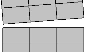
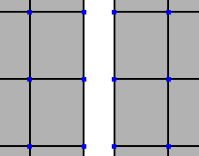
Welding edges merges one or more pairs of facing boundaries on a single polygon mesh object. Bridging adds polygons between pairs of facing boundaries on a single polygon mesh object.
You can use these features to "zip" up opposite boundaries (if two edges are selected) or to restrict the effect to the edges you specify (if more than two edges are selected).
To weld or bridge selected edges
If you select more than two edges first, the welding or bridging operation is restricted to the selected edges. You can still use the Distance parameter to specify a tolerance for welding or bridging specific pairs of edges.
Select the boundary edges that you want to weld or bridge. You can specify how the selection is interpreted by setting Target in step 3.
You can also specify edges by selecting all their adjacent points. Non-boundary edges are ignored. If you select a polygon mesh object, all boundaries are merged.
Choose Modify Poly. Mesh Weld Boundary Points/Edges or Modify Poly. Mesh Bridge Boundary Points/Edges from the Model toolbar.
The WeldEdges Op property editor opens and the Grow Selection option is not available. Adjust the options as desired:
Distance controls the tolerance between facing edges. As you increase this value, more pairs of edges get affected.
Target specifies which edges to weld, when an appropriate pair of candidates is found: Input Edges welds pairs of selected edges with each other; Other Edges welds each selected edge with an unselected edge; and All Edges welds each selected edge with any other selected or unselected edge.
Bridge controls the behavior for connecting edges.
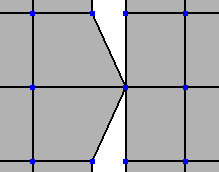
When this option is off, pairs of facing edges are merged. This option is off by default if you chose Weld Boundary Points/Edges,
When this option is on, pairs of edges get connected by new polygons. This option is on by default if you chose Bridge Boundary Edges.
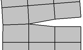
You can use the Grow Selection option to "zip" up opposite boundaries only if you select no more than two edges first.
Select one edge on one of the boundaries you want to weld or bridge.
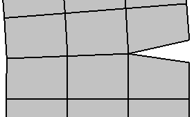
If desired, add the corresponding edge on the opposite boundary to the selection.
If you do not specify the second edge, the closest opposite boundary will be used automatically.
Choose Modify Poly. Mesh Weld Boundary Points/Edges or Modify Poly. Mesh Bridge Boundary Edges from the Model toolbar.
The WeldEdges Op property editor opens and the Grow Selection option is available. Adjust the options as desired:
Distance controls the tolerance between facing edges. As you increase this value, more pairs of edges are affected.
Bridge controls the behavior for connecting edges.
When this option is off, pairs of facing edges are merged. This option is off by default if you chose Weld Boundary Points/Edges.
When on, pairs of edges get connected by new polygons. This option is on by default if you chose Bridge Boundary Edges.
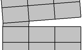
Grow Selection allows boundaries adjacent to the ones you picked to be welded as well. Turn this option off to weld only the two original boundaries.
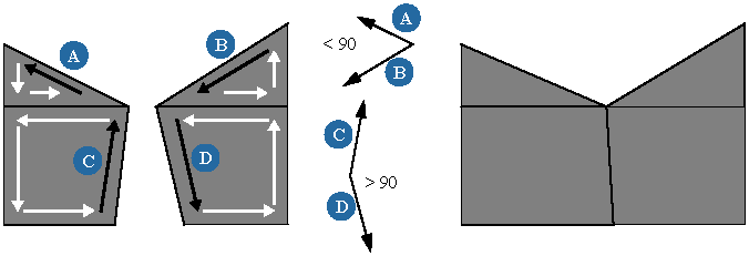
Angle 90 welds two boundaries only if the difference between their orientations is greater than 90 degrees. This prevents the zipping
effect from welding pairs of edges that are not facing each other. When considering the orientation of edges, remember that
edges are ordered counterclockwise when normals face you.
You can split edges interactively with the Split Edge tool or with numerical accuracy using the Split Edge (with split control) command. Both methods allow you to automatically split parallel edges and join the new vertices. You can also split edge loops while preserving curvature continuity using the Add Smooth Edge Loop tool. In all three cases, a SplitEdge operator gets added to the object's construction stack.
The Split Edge tool lets you interactively add vertices along existing edges. You can also automatically split parallel edges and join the new vertices.
Choose Modify Poly. Mesh Split Edge Tool from the Model toolbar or press ].
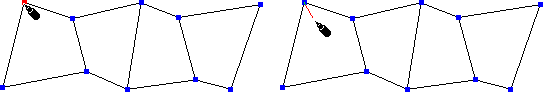
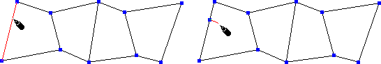
Move the pointer over an existing edge. The targeted edge turns red.
To add a new vertex, click at the desired position along the targeted edge.
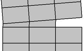
To automatically add and join new vertices along parallel edges, click the middle mouse button. Note that this works best with a row of quadrilateral polygons.
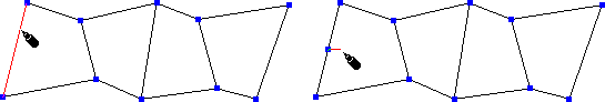
You can bisect the edge evenly by pressing Ctrl while clicking.
You can adjust the position of the new vertex along the edge by moving the mouse before releasing the mouse button. However, unlike the Add Vertex tool described in Adding Vertices, you can move the new vertex only along the edge.
If you are having difficulty splitting an edge near an existing vertex, try zooming the view.
When you have finished splitting edges, exit the Split Edge tool by right-clicking.
To split edges with numerical accuracy
The Split Edge command splits edges with numerical accuracy. You can also automatically split parallel edges and join the new vertices.
Choose Modify Poly. Mesh Split Edge (with split control) from the Model toolbar. The SplitEdge Op property editor opens.
Ratio Edge determines where the new vertex is placed along an edge.
Parallel Edge Loop additionally splits edges parallel to those selected. Note that this works best with a row of quadrilateral polygons.
Connect adds edges connecting the newly created vertices. This has an effect only when Parallel Edge Loop is on.
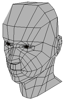
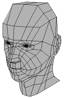
The Add Smooth Edge Loop tool splits parallel edges across quad topology while preserving the original surface curvature continuity.
Choose Modify Poly. Mesh Add Smooth Edge Loop Tool from the Model toolbar.
As you move the mouse, the edge under the pointer is highlighted. Do one of the following:
The tool stays active so you can continue adding loops. In addition, you can right-click to:
The Split Polygon tool lets you interactively subdivide n-sided polygons into n new polygons. For example, a triangle splits into three new polygons, a quad splits into four new polygons, and so on.
Choose Modify Poly. Mesh Split Polygon Tool from the Model toolbar.
Move the pointer over an existing polygon. The targeted polygon turns red.
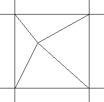
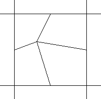
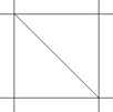
Left-click to split the targeted polygon by drawing edges from the point you clicked to each edge. In the case of quadrilateral polygons, two collinear pairs of edges are created, resulting in a cross shape.
Middle-click to draw new edges from the point you clicked to each vertex of the targeted polygon.
Right-click to draw new edges from the point you clicked to the midpoint of each edge of the targeted polygon.
If desired, you can activate snapping while using this tool. For more about snapping see Snapping.
When you have finished splitting polygons, exit the Split Polygon tool by pressing Esc or choosing another tool.
Subdividing Polygons and Edges
You can subdivide polygons and edges evenly using the Subdivide Polygons/Edges command. The options are different for each component type.
As an alternative to using this command to subdivide polygons, you can also apply local subdivision as described in Subdividing Polygons Locally.
Select some polygons, polygon clusters, or polygon mesh objects.
Choose Modify Poly. Mesh Subdivide Polygons/Edges from the Model toolbar or press Shift+D.
In the SubdividePolygon Op property editor, set the options as desired:
Subdivision Type determines the shape of the new polygons:
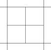
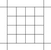
Plus adds edges from the geometric center of a polygon to the midpoint of each edge.
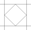
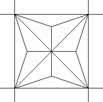
Diamond draws edges connecting the midpoints of a polygon's edges.
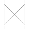
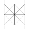
X draws edges from the midpoint of a polygon to each of its vertices.
Triangles triangulates all quad and n-sided polygons.
Iterations controls how many times the process is repeated on the polygons that are created at each step. This option has no effect when Subdivision Type is Triangles.
Tile has a visible effect only when both Subdivision Type is Diamond or X and Iterations is greater than 1.
When it is on, all but the last iteration is of the type Plus and the final subdivision is of the type specified. This gives a tile-like pattern when working with quadrilateral polygons.
Choose Modify Poly. Mesh Subdivide Polygons/Edges from the Model toolbar.
In the SubdivideEdge Op property editor, set the options as desired.