You can identify the objects that have constraints on their parameters in the 3D views and in the schematic view. As well, you can use a constraint query to get information about the constraints on an object.
To view constraints in a viewport
In any viewport title bar, click the eye icon and choose Relations.

When you select a constrained object, a white line linking it to its constraining object is displayed. The link is labeled with the type of constraint, such as Pos for a position constraint.
When you select a constraining object, a light purple (lavender) line linking it to its constrained object is displayed.
For direction constraints, a link with an arrow at one end shows the relationship between the constrained and constraining object (the large arrow points to the constraining object).
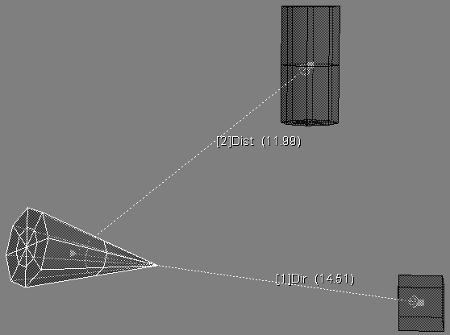
Below, the cone is constrained by Distance to the cylinder and by Direction to the cube. When you select the cone, white link lines to its constraining objects are displayed. Each link displays the name of the constraint type.
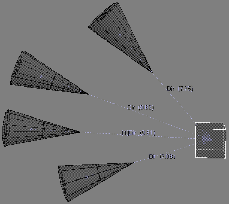
Below, four cones are constrained by Direction to a cube. When you select the cube, light purple link lines to the constrained objects are displayed, each one displaying the name of the constraint type.
To view constraint relations information
Click the eye icon in a viewport and choose Visibility Options (or press Shift+S).
From the list of options on the Attributes page in the Visibility Settings property editor, you can choose to show Relations icons or Relations Information for selected or unselected objects, or both.
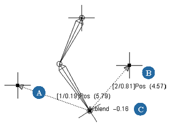
| A |
The constraint link. Select this and press Enter to open the constraint's property editor. |
| B, C |
Constraint relations information shows priority and blending value between the constraints. |
The relations information shows whether the constraint is deactivated (off), the constraint's priority (the order in which is was applied in the case of multiple constraints — 1, 2, 3, etc.), and its blended weight value (if multiple constraints are blended).
If there are multiple offsets on the object's constraints, two arrows and their distance displays tell you the length of each link.
Open a schematic view and choose Show  Constraint Links, then select a constrained or constraining object.
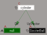
A constrained object has the letter C above its node. A green arrow with the name of the constraint type (such as Direction, Position, UpVector, etc.) links objects that are affected by a constraint.
Finding Constraint Elements in the Explorer
You can select a constrained object and then use an explorer to find its constraint properties.
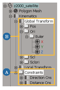
| A |
Expand the constrained object's Kinematics Click the constraint's name to select it, or click the constraint's icon to open its property editor. Right-click the Constraints folder to open a menu where you can choose Properties to open a property editor showing all constraints in this folder. You can also activate, deactivate, or delete all constraints in that folder using the menu. |
| B |
When an object is constrained, its corresponding Global Transform parameters are controlled by a constraint. For example, the Direction constraint controls the orientation (Ori) parameters, while the Distance constraint controls the position (Pos) parameters. The parameter's animation icon changes from its default green box to a letter C and a connection. See The Animation Icon for more information about the different states of the animation icon. 
|