The operator stack (also known as the modifier stack or construction history) is fundamental to modeling in Softimage. It is the history of all the operators (such as deformations and topology modifications) that have been applied to an object, and is divided into regions for modeling, animation, and shapes. Operators propagate their effects upwards through the stack, with the output of one operator being the input of the next. At any time you can go back and modify or delete operators in the stack.
Viewing and Modifying Operators
You can view the operator stack of an object in an explorer if Operators is active in the Filters menu. The operator stack is under the first subnode of an object in the explorer, typically named Polygon Mesh, NURBS Surface Mesh, NURBS Curve List, Null, and so on.
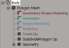
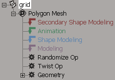
For example, suppose you get a primitive polygon mesh grid, apply a twist, then randomize the surface. The operator stack shows the operators that have been applied. You can open the property page of any operator and modify values. Any changes you make are passed up through the history and reflected in the final object.
You can display the property editor for any operator in the stack and modify its parameters.
To open the property editor of a single operator
You can open the property editor of a specific operator using either an explorer view or the transient explorer available from the Selection button in the main command area.
If you are using an explorer view, make sure that Operators is active in the Filters menu. The object with the operator does not need to be selected.
If you are using the Selection button, you must first select the object with the operator.
In either case, do one of the following:
To open the property editors of all modeling operators applied to an object
In a schematic or explorer view, right-click an object and choose Modeling Properties. The object does not need to be selected.
In a 3D view, Alt+right-click (or Ctrl+Alt+right-click on Linux) on an object and choose Modeling Properties. Again, the object does not need to be selected.
Select the object then choose Edit  Properties Modeling Properties from the Edit panel.
A single property editor opens with each operator's parameters available on separate tabs.
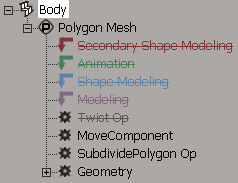
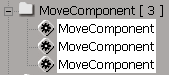
If you apply the same operation to an object several times in a row, the multiple occurrences of the same operator are automatically grouped together under an expandable folder in the stack and the number of occurrences is shown in square brackets.
This simplifies the view in the explorer — for example, you see a single MoveComponent folder node instead of hundreds of MoveComponent nodes. Clicking on the folder name selects all the operators in the folder.
Operators are divided into several categories, based on the type of information they change:
Generators create an object. These include most of the operators available from the Get Primitive menu, as well as those under Create. Examples include Geometry (primitive), CurveCreation, Loft, NURBS to Mesh, and so on.
Topology operators change the geometry, for example, by adding or removing components. These include most of the operators available under Modify. Examples include Curve Shift, Insert Surface Knot, Subdivide Polygon, and so on.
Deformations modify the shape of an object by changing the positions of its points. These include the operators available from the Deform menu, as well as the Move Component and Envelope operators.
Construction Modes and Regions
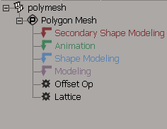
The construction history is divided into four main regions: Modeling, Shape Modeling, Animation, and Secondary Shape Modeling. The purpose of these regions is to keep the construction history clean and well ordered by allowing you to classify operators according to how you intend to use them. For example, when you apply a deformation, you might be building the object's basic geometry (Modeling), or creating a shape key for use with shape animation (Shape Modeling), or creating an animated effect (Animation), or creating a shape key to tweak an enveloped object (Secondary Shape Modeling).
You add operators to specific regions by selecting a construction mode before you perform a modeling operation, as described in Setting Construction Modes. If you unintentionally added an operator in the wrong mode, you can move the operator to the correct region as described in Changing the Order of Operators.
As you work, you can display the final result (the result of all operators in all regions) or just the current mode (the result of all operators in the current region and those below it) as described in Displaying the Results of Different Regions.
By default, each view shows information about the current construction mode and display mode. You can toggle this feedback on or off as described in Getting Feedback on the Current Modes.
There are two additional construction regions that are used for ICE simulations. They appear automatically when you create a ICE simulation operator. For information that is specific to these regions, see ICE Trees and the Construction Stack.
About the Construction Regions
Each of the four main construction regions is intended for a different purpose:
The Modeling region is at the bottom. You can use this region to define the basic shape and topology of an object using both deformations and topology operators.
This is often the region you want to freeze for performance reasons. You can freeze the Modeling region without affecting the other regions as described in Freezing the Operator Stack.
You can include animated operators in the Modeling region, if desired. However, the animation will be lost if you freeze the modeling. In addition, if there is shape animation above an animated deformation in the stack, there is a danger that shapes will "pop" when polygons intercollide.
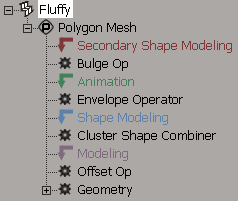
The Shape Modeling region is above the Modeling region. In addition to containing the Cluster Shape Combiner node, this region lets you apply deformations to define shape keys for shape animation. When you store a shape key in Shape Modeling mode, the effect of the operators in this region are stored in the shape key. When you create a shape clip by applying a key, only the operators in this region are removed — this protects animated deformations that may be present in the Animation region, such as envelopes, from being removed.
The Animation region is above the Shape Modeling region. You can use it for animated deformations that you don't want to be removed when you freeze the modeling or apply a shape, for example, deformations such as envelopes, waves, cages, lattices, spines, or even a simple Push with an animated amplitude.
The Secondary Shape Modeling region is at the top. You can use it to create shape keys for things like muscle bulges on top of an enveloped character. Like the Shape Modeling region, the effect of the operators in this region are stored when you store a shape key in Secondary Shape Modeling mode, and the operators in this region are removed when you create a shape clip by applying a key.
Note that all shape keys are applied at the level of the Cluster Shape Combiner at the bottom of the Shape Modeling region, including shapes created in Secondary Shape Modeling mode. This means that Softimage must calculate the inverse deformation of any operators in the Animation region when it creates the shape key. As a result, shapes work well if there is only an envelope operator in the Animation region, but they might not always give the desired results when there are non-envelope deformations in the Animation region. This is unavoidable because not every deformation has an inverse.
In explorers, the tops of each region are indicated by special markers that act as placeholders. The markers are created automatically as soon as you apply the first operator, and can be moved like other operators as described in Changing the Order of Operators. However, you cannot change the order of the markers by moving one marker above or below another one. In addition, the Cluster Shape Combiner must always be at the bottom of the Shape Modeling region.
When you open or import a scene or model created in Softimage version 3.5 or earlier:
If an object has shape animation, the position of the Cluster Shape Combiner node determines the start of the Shape Modeling region.
If an object has no shape animation, all operators are placed in the Modeling region.
You can then move operators to specific regions as described in Changing the Order of Operators.
Here is a quick overview of the workflow for using construction modes:
Set the construction mode as described in Setting Construction Modes.

Continue modeling objects by applying new operators.
New deformations are applied at the top of the current region, and new topology modifiers are always applied at the top of the Modeling region.
You can change operators' regions after they have been applied by moving operators in the stack, but the usual caveats still hold (see Changing the Order of Operators).
At any time as you work, you can display the final result (the result of all operators in all regions) or the just the current mode (the result of all operators in the current region and those below it) as described in Displaying the Results of Different Regions. You can even have different displays in different views so, for example, you can see and move points in one view in Modeling mode while you see the results after enveloping and other deformations in another view.
By default, each view shows information about the current construction mode and display mode. You can toggle this feedback on or off as described in Getting Feedback on the Current Modes.
The current construction mode determines the construction region to which new deformation operators are added. You can choose the mode based on what you want to do.
For example, suppose that you want to apply a deformation by spine:
If you are sculpting an object's basic shape with the spine deformation and intend to freeze it when you are finished, use Modeling mode.
If you will be using the spine deformation to store shape keys for the basic shape, use Shape Modeling mode.
If you will be animating the object by animating the spine curve's shape, use Animation mode.
If you will be using the spine deformation to store shape keys such as muscle bulges on top of an enveloped object (that is, in relation to the envelope's animation), use Secondary Shape mode.
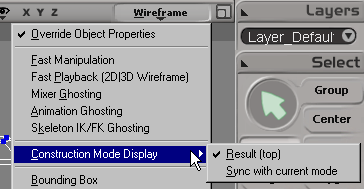
Choose the desired construction mode from the selector on the main menu bar.
If you can't see the mode selector, right-click in an empty area of the main menu bar and activate Construction Mode.
New deformations will be added to the top of the corresponding construction region until you change modes again.
To change construction mode automatically
The Construction Mode - Enable Auto Update option in the Modeling preferences controls whether the construction mode changes automatically when you perform certain operations. When this option is on, the following changes happen automatically:
Applying a topology operator automatically switches to Modeling mode.
Applying an envelope and responding "Yes" when prompted to apply it in the Animation region automatically switches to Animation mode.
Saving or storing a shape key automatically switches to Shape Modeling mode when you are in Modeling mode, or Secondary Shape Modeling mode when you are in Animation mode.
Displaying the Results of Different Regions
The construction display mode determines how objects are displayed in 3D views. The possible values are:
Result (top) always shows the final result of all operators, no matter which construction mode is current.
Sync with construction mode shows the result of the operators in the current construction region and below.
You can continue to apply deformation and topology operators no matter which region is displayed. You can even have different displays in different views so, for example, you can see and move points in one view in Modeling mode while you see the results after enveloping and other deformations in another view.
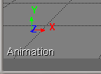
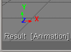
Getting Feedback on the Current Modes
You can see information about the current construction mode and display mode in the 3D views. You can toggle this feedback on or off as desired.
Special Considerations for Topology Modifications
There are a few things you should be aware of when there are operators that modify the topology in the stack.
Animating or Modifying Generators and Topology Operators
When a generator or topology operator exists below other operators in the stack, you must be very careful when modifying or animating its parameters. If the amount of geometry changes, then the indices of components will also change. This can have an adverse affect on other operators higher in the stack if they rely on clusters or component indices.
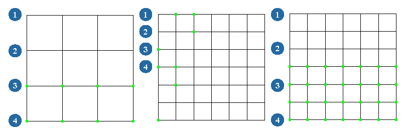
For example, suppose you get a primitive polygon mesh grid and then create a cluster on it. If you reopen the primitive Geometry property editor and increase the Subdivisions, the cluster shifts because the new points are being added at a point in the stack earlier than where the cluster is defined — this also affects any operator such as MoveComponent that may use the cluster as an input.
However, if you apply a SubdividePolygon operator after you create the cluster, the cluster does not shift because the new points are created after the cluster.
Topology Operators and Shape Animation
If you intend to modify or animate the parameters of a topology operator on an object with shape animation, then you should apply that topology operator after authoring all your shapes. The topology operator will be inserted in the modeling region below the Cluster Shape Combiner, but the shapes will update correctly. The shape animation does not require the topology operator to be re-evaluated, and you can freeze the topology operator without affecting the shapes.
For example, you can take a shape-animated object and apply polygon reduction to create one or more low-resolution versions of the object. In this way, all the shapes and transitions are preserved. However, if you apply polygon reduction first and then create the shape animation, the shapes are not correct when you change the amount of reduction.
Modifying Clusters Below Topology Operators
When you modify existing clusters or cluster-based properties, you may get no results or incorrect results if there are topology operators higher up in the stack. Such situations include:
Adding or removing components from a cluster that is created below a topology operator in the stack. This includes clusters that are created automatically when you apply deformations or properties to selected components.
Modifying weight map values (including envelope weights) when there is a topology operator above the weight map creation point or Envelope Operator in the stack.
Modifying vertex colors when there is a topology operator above the Color at Vertices map creation point in the stack.
In these situations, you should simply disable all topology operators above the cluster creation point before modifying the cluster or property. When you have finished, re-enable the top of the stack and the object updates properly.
For more information about disabling operators, see Disabling the Top of the Stack.
Topology Operators and Dependency Cycles
When you apply a topology operator, Softimage checks to ensure that no new dependency cycles are created. A dependency cycle is a situation where one or more inputs of an operator depend on its output, possibly through some route involving other operators and clusters. This can lead to corruption and instability.
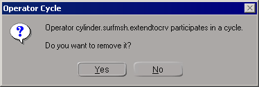
When Softimage detects a new dependency cycle, it prompts you to remove the new operator. It is strongly recommended that you click Yes to delete the last operator applied. Clicking No and leaving the operator in the scene can lead to eventual problems.
After you remove the operator, you can check the command log to see which operators participated in the cycle. You may need to freeze the associated objects before applying the operator again.
Changing the Order of Operators
You can change the order of operators in an object's stack by dragging and dropping them in an explorer view. You must always drop the operator onto the operator or marker that is immediately below the position where you want the dragged operator to go.
Be aware that you might not always get the results you expect, particularly if you move topology operators or move other operators across topology operators, because operators that previously affected certain components may now affect different ones. In addition, some deformation operators like MoveComponent or Offset may not give expected results when moved because they store offsets for point positions whose reference frames may be different at another location in the stack.
When you try to drag and drop an operator, Softimage evaluates the implications of the change to make sure it creates no dependency cycles in the data. If it detects a dependency, it will not let you drop the operator in that location. Moving an operator up often works better than moving it down — this is because of hidden cluster creation operators on which some operators depend.
If you drag an operator to a new location and then drag it back to its original location, you might not get the original results. This is due to internal dependencies on clusters. However, if you undo after dragging an operator, you will always get the original results.
You can also drag and drop a texture operator to control whether a projection sticks or swims. See Dragging and Dropping Texture Operators in the Stack
One exception to these rules is the Surface Continuity Manager operator (SCM Fixer Op2): you cannot move this operator and it is always at the top of the stack. Another exception is the Cluster Shape Combiner: it is at the bottom of the Shape Modeling region by default and cannot be moved (although you can move other operators immediately below it).
Changing the Order of Operators Using Script Commands
When you move an operator by dragging and dropping in an explorer, the CopyPaste command is logged to the command history.
However if you want to move operators using scripts, you can also use the SwapOps, MoveOperatorAfter, and MoveOperatorBefore commands. If these commands fail, they provide more precise error messages than CopyPaste.
For more information about scripting in general, see Script Development [SDK Guide].
Disabling the Top of the Stack
If you need to insert new operators in the middle of the stack, you can disable the stack from any operator up to the top. New operators are added to the active portion of the stack until you re-enable the top of the stack.
Disabling the stack is temporary. If you save and reload the scene, the stack is re-enabled.
Follow these guidelines when disabling the top of the stack; otherwise, you may get unpredictable results.
To disable the top of the stack
In an explorer view, right-click the lowest operator you want to disable and choose Disable from Here.
The operator and everything above it no longer affect the object and appear dimmed with strike-through text.
You can continue to disable other operators even lower in the stack to disable in stages.
When you are satisfied with an object, you can freeze all or part of its operator stack. This removes the current history — as a result, the object requires less memory and is quicker to update. However, you can no longer go back and change values.
You can freeze the modeling region, freeze the entire object, or freeze the bottom of the stack from a particular operator down.
To freeze the bottom of the operator stack
In an explorer, do one of the following:
Select an operator in the stack, and then click Freeze on the Edit panel.
Select an operator in the stack, and then choose Edit Operator Freeze Selected.
The selected operator and everything below it in the stack is collapsed, including any weight maps and texture projections that were applied below the selected operator.
Collapsing Deformation Operators
Sometimes, it is useful to "freeze" certain operators in the stack without freezing earlier operators that are lower in the stack. For example, you might have many MoveComponent operators that are slowing down your scene, but you don't want to lose an animated deformation or a generator (if your object has a modeling relation that you want to keep).
Another situation where this would be useful is when you need to change the behavior of particular deformations. For example, if you apply a Bulge deformation, scale some points, and adjust the Bulge operator's amplitude, you'll see that the scaling is multiplied by the bulge effect. If you want an additive effect, you need to somehow "freeze" the MoveComponent operator created by scaling the points.
In these cases, you can collapse several deformation operator into a single Offset operator. The Offset operator is a single deformation that contains the net effect of the collapsed deformations at the current frame. The Offset operator has no parameters and no property editor.
When collapsing operators, here are some things you should know:
Only deformations can be collapsed. You cannot collapse topology operators.
You cannot collapse across topology operators. If a topology operator is in the middle of a set of deformation operators to be collapsed, two Offset operators are created: one above the topology operator and one below it.
You cannot collapse across points in the stack where other operators read information, even though you cannot see these points in the stack.
For example, if you apply a Randomize deformation, create a texture projection, apply a Push deformation, then select the deformations and collapse them, two Offset operators are created because the texture projection is reading data from the point in-between. If you freeze the texture projection, you can then collapse the deformations into a single Offset operator.
If the collapsed deformations contained any animated parameters, the animation is lost when you collapse them.
If the collapsed deformations had any object inputs (such as envelope or spine deformers), that relation is lost after you collapse them.
If you modify operators below an Offset operator, the overall effect might change.
For example, let's say you have a Lattice deformation, followed by a Twist, and then you collapse the Twist into an Offset operator. If you then modify the lattice, you'll notice that the Offset operator still applies the same relative offset to each point, but depending on how you modify the lattice, it is no longer really a "twist".
Offset operators are deformations like any other and can also be collapsed.