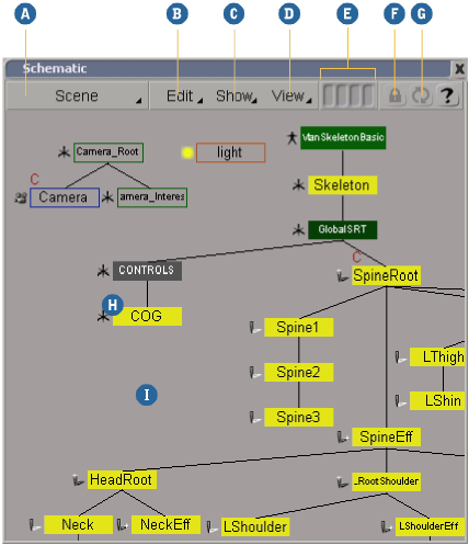
The schematic view presents the scene in a hierarchical structure so that you can analyze the way a scene is constructed. It includes graphical links that show the relationships between objects, as well as material and texture nodes to indicate how each object is defined.
Press 9 (use the key at the top of the keyboard, not the numeric keypad) or choose View  General Schematic from the main menu to open in a floating window.
Choose Schematic from a viewport's Views menu to open it docked in that viewport.

Selecting Elements in the Schematic View
Selecting Objects in the Schematic View
When the Select tool is active, you can select objects by clicking on them, and you can select multiple objects by dragging a rectangle across them. Use the left mouse button for node selection, the middle mouse button for branch selection, and the right mouse button for tree selection.
You can also click a parent-child link to select the child. This is useful if you have located the parent but can't find the child in a jumbled hierarchy. Again, use the left, middle, or right mouse buttons to select the child in node, branch, or tree modes.
When other types of link are displayed, you can click the link to select the corresponding operator. For more details, see Selecting Properties [Scene Elements].
The Select tool is active by default. If you have activated a different tool, you can re-activate the Select tool by doing one of the following:
The selection filters set on the Select panel are obeyed when selecting in the schematic view.
For more information about selection in general, see Selecting [Scene Elements], and in particular Selecting Objects.
Displaying Scene- Element Information
Scene elements in the schematic view are displayed as graphical nodes. You can use the filters in the Show menu to determine which types of object are visible in the schematic, as described in Using Filters to Further Define the View.
Objects that are visible in the 3D views are shown as solid rectangles in the schematic view. Objects that are hidden in the 3D views are shown as outlines and are selectable in the schematic view.
Relationships between elements are displayed as lines called links. You can display or hide links for different types of relationship as described in Displaying Links (Relationships) Between Elements.
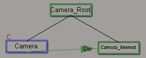
A letter identifier provides additional information about nodes. For example, the letter C indicates that a node is a constrained object. For a list of letters that may appear, see Letters and Their Meaning.
Choose View Show Icons to display icons representing the element types as in the explorer.
When the Select tool is active, you can click an icon to open the element's property editor.
This setting is saved in your preferences and used for all scenes you work on.
Opening Property Editors for Elements
If icons are not visible, you can still open an element's property editor by double-clicking on it with either the Selection tool or the Pick and Move tool.
You can also open an element's property editor by selecting it and pressing Enter.
Displaying an Element's Property Nodes
You can display an element's set of property nodes in a pop-up explorer by right-clicking on the element and choosing Explore.
Displaying Links (Relationships) Between Elements
You can display links between nodes that have a relationship, such as a constraint, operator dependency, or simulation (like forces). To toggle the display of a specific type of link, choose Show (Link Type). Hold the Shift key to keep the menu open and toggle several items at once.
To toggle between displaying links for all objects and displaying links for only nodes that are selected, choose Show Links on Selected Nodes Only. This option can simplify the view shown in the schematic, allowing you to concentrate on the links between specific objects.
Link types are generally drawn in a similar color to the corresponding toolbar, so operator links are purplish (Model toolbar), constraint and expression links are green (Animate toolbar), material links are blue (Render toolbar), and simulation links are horny salmon (Simulate toolbar).
You can select links by clicking and dragging across them. When a link is selected, you can press Enter to open the property editor related to the associated relationship (if applicable), or press Delete to remove a relationship like a constraint or expression.
The View Parallel Links option controls whether parent-child links are drawn as straight lines or as vertical and horizontal segments. This option
is saved in your preferences, and used for all scenes you work on.
If links do not display correctly, press F5 to refresh the display for the selected node. If nothing is selected, F5 refreshes all nodes in the scene.
Some nodes and links may have letters superimposed on them, depending on their properties.
You can choose which elements of the scene hierarchy to display by selecting an option from the schematic view's menus.
Defining the Scope of the Hierarchy View
You can define which elements to display in the scene hierarchy by choosing an option in the scope menu:
Using Filters to Further Define the View
You can use the filter commands found in the Show menu to display or hide nodes based on their types. For example, you can display or hide geometric objects, kinematic chains, or material nodes. This lets you focus on the elements you want to work on, or simply reduce the amount of information displayed for easier selection.
Locking the View onto Selected Objects
The Selection option in the schematic view's scope menu displays only the nodes of objects that are currently selected.
If you click the Lock button with the Selection option active, the schematic view continues to display the nodes of the currently selected objects, even if you go on to select other objects using other views. Click Lock a second time to switch off the lock feature.
When Lock is on, you can also select another object and click Update to lock on to it and update the display.
You can choose the color used to display unselected object nodes in the schematic view:
Choose View Use Standard Colors to display unselected objects in black.
Choose View Use Wire Colors to display unselected objects using their wire color. To specify an object's wire color, see Choosing How to Display Specific Objects [Viewing and Playback].
Choose View Diffuse Colors to display unselected objects using the diffuse component of their material.
In all cases, selected objects, branch-selected objects, and owners of the subselection are displayed using the colors specified in the Scene Colors property. For more information about setting scene colors, see Setting Scene Colors [Viewing and Playback].
The option you choose is saved in your preferences. It is used for all scenes you work on.
Navigating in the Schematic View
The schematic view's View menu contains a number of navigation commands:
To focus only on the selected objects in the hierarchy
Note that if the selected object is inside a collapsed hierarchy, nothing happens. For more information about collapsing and expanding hierarchies, see Expanding and Collapsing Hierarchies.
By default, you can zoom using the mouse wheel. Scroll forward to zoom in and backward to zoom out. Press Ctrl to zoom quickly, Shift to zoom more slowly, and Ctrl+Shift to zoom even more slowly.
If desired, you can disable the mouse wheel zoom or restrict it to the Navigation tool so that you can use the mouse wheel with other tools. See Mouse Wheel in Camera Preferences [Preference Reference].
You can move nodes around in the schematic view, for example, if you want to create patterns that visually indicate the relationship among elements. To change the underlying order of child nodes, see Reordering Child Nodes in the Schematic.
You can use the Pick and Move tool to rearrange nodes without changing the selection, or you can select the nodes you want to move first and then use the Translate tool.
When you move a node manually, its position becomes locked relative to the root of its hierarchy. This means that it is no longer affected when the hierarchy is rearranged manually or automatically. Before you can rearrange a position-locked node, you must reset its user position (see Resetting User Positions). Position-locked nodes are indicated with a 1-pixel border (although the border is not drawn when the view is zoomed very far out).
To move nodes using the Pick and Move tool
Arranging Nodes Horizontally or Vertically
Two options on the View menu control the placement of child nodes relative to their parents:
View Vertical Layout places child nodes below their parents.
View Horizontal Layout places child nodes to the right of their parents.
When you choose either of these options, the entire schematic view is automatically rearranged. This option is saved in your preferences and is used for all scenes you work on.
Rearranging a hierarchy "cleans" it by automatically moving child nodes according to the current View setting (Vertical Layout or Horizontal Layout). Nodes that have been positioned manually are not moved unless you reset their positions first.
After you have moved a node manually, it becomes position-locked relative to the root of its hierarchy. This is indicated by a 1-pixel border.
Position-locked nodes are not affected when a hierarchy is rearranged. To rearrange a position-locked node, you must first reset its user position.
You can reset the user positions of specific nodes, or reset all nodes at once.
To reset the user positions of specific nodes
Alt+right-click on a node, and choose Reset User Position(s) from the pop-up menu.
If the node you clicked on was selected, the user positions of all selected nodes (including branch-selected nodes) are reset.
If the node you clicked on was not selected, only its user position is reset.
The affected nodes are no longer position-locked and 1-pixel border is removed. The nodes will be affected the next time you rearrange the hierarchy.
You can rearrange the hierarchies in the schematic view according to various criteria.
Choose one of the options from the View Overall Sort submenu:
None (creation) does not sort the hierarchies at all. The default order is based on the order of creation of the root nodes.
by Type puts cameras first, followed by lights and then other 3D objects.
by Height/Width places the hierarchies in order of tallest to shortest. When two hierarchies have the same height, the one that is wider is placed before the other.
by Width/Height places the hierarchies in order of widest to narrowest. When two hierarchies have the same width, the one that is taller is placed before the other.
Expanding and Collapsing Hierarchies
You can expand or collapse any hierarchy or sub-hierarchy in the schematic diagram to simplify the view.
Rearranging Automatically When Parenting or Cutting Children
The View Clean Hierarchy Upon Structure Change option controls whether nodes in the schematic view get rearranged when you change a hierarchy by parenting or cutting children.
Building Hierarchies in the Schematic View
In addition to creating parent-child relationships in the schematic view, you can reorder child nodes.
Creating Hierarchies in the Schematic View
For more information about hierarchies in general, see Creating Hierarchies [Scene Elements].
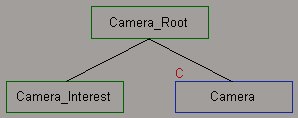
Reordering Child Nodes in the Schematic
By default, the child nodes are ordered according to when they became children of their parent. This order is reflected in
the schematic view when rearranging nodes (if View Overall Sort is set to None (creation)) as well as in the explorer view. The order is also used when selecting the next or previous sibling using the buttons on
the Select panel or the Alt+arrow keys.
You can change this underlying order in two ways: by using the Reorder Nodes tool, or by arranging the hierarchy visually and then freezing the ordering.
To reorder siblings using the Reorder Nodes tool
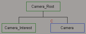
Drag and drop a node to a new position before, after, or between its siblings, either horizontally (if View Vertical Layout is on) or vertically (if View Horizontal Layout is on).
For example, if View Vertical Layout is on and you drop a node to the left of all its siblings, it becomes the first child. Similarly, if View Horizontal Layout is on and you drop a node above all its siblings, it becomes first.
Each time you drop a node, the hierarchy below its parent is automatically rearranged and cleaned.
To reorder siblings by freezing the order
Use the Pick and Move tool or the Translate tool to arrange the children of a node in the order you want from right to left
(if View Vertical Layout is on) or top to bottom (if View > Horizontal Layout is on). For more information, see Moving Nodes Manually.
Alt+right-click (Ctrl+Alt+right-click on Linux) on the parent node and choose Freeze Child Ordering from the pop-up menu.
The node's immediate children are reordered. User positions are reset and the hierarchy is cleaned.
To reorder hierarchy roots by freezing
Use the Pick and Move tool or the Translate tool to arrange the roots of hierarchies in the order you want from right to left
(if View Vertical Layout is on) or top to bottom (if View Horizontal Layout is on). For more information, see Moving Nodes Manually.
Choose View Freeze Root Node Ordering.
All root nodes (direct children of the scene root) are reordered. User positions are reset and the hierarchy is cleaned.


