You can apply visual effects to the 3D View using the Viewport Filters. These filters can enhance your sculptures and assigned materials and aid in recreating an environment that mimics how they’ll be rendered in another application. When turned on, these filters appear as a post-processing effect that is applied in real-time to everything displayed in the 3D View.
You can save an image of the 3D View using Save Screen Image. For more information, see Save an image of the 3D View.
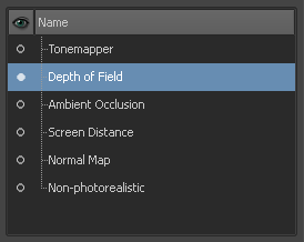
You can turn on the following filter effects to modify how the model appears in the 3D View (provided your computer graphics card supports these Cg-based effects):
The Tonemapper filter works by remapping the color values for what displays in the 3D View. Adjust the Tonemapper properties to compress, expand, or shift the tonal range of the rendered scene.
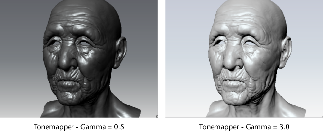
You can also simulate interesting glow effects using the Glare property. This feature is useful when you use HDRI images for environment and material maps and you need to evaluate the model with an overall level of brightness or contrast applied.
Using the Depth of Field filter
The Depth of Field filter lets you simulate the depth of field effects inherent to optical camera lenses in real time. That is, a specific near and far range from the camera can be defined where items within the specified range appear in focus and items outside the specified range appear out of focus, or blurred.
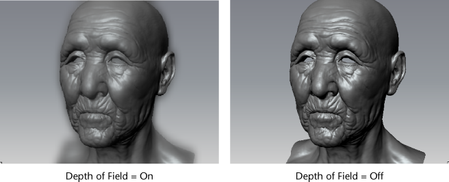
Depth of field helps to reduce the overall digital sharpness that is inherent to computer graphics and makes a model appear with characteristics inherent to an optical camera lens.
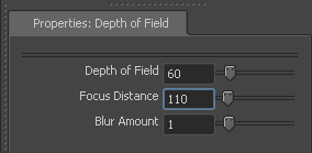
The properties appear in the Properties window.
Using the Cavity Ambient Occlusion filter
The Cavity Ambient Occlusion filter lets you simulate the occlusion effects that darken cracks, crevices, corners and points of contact on rendered surfaces.
This filter aids in evaluating the overall 3D form of a model in fine detail areas, much like moving a light across the front of the surface helps to evaluate the surface highlights and subtleties of its overall form.
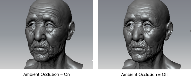
Using the Ambient Occlusion filter
The Ambient Occlusion filter lets you simulate the occlusion effects that darken cracks, crevices, corners and points of contact on rendered surfaces.
This filter aids in evaluating the overall 3D form of a model in fine detail areas, much like moving a light across the front of the surface helps to evaluate the surface highlights and subtleties of its overall form.
 ) menu.
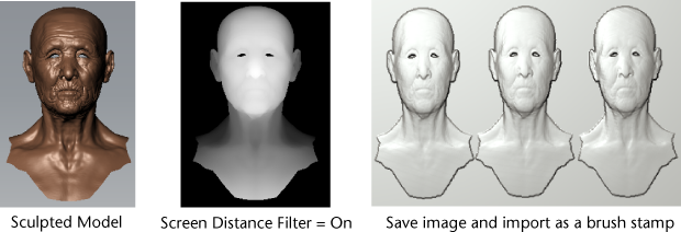
Using the Screen Distance filter
Screen Distance is useful for quickly creating stencils, stamps, or displacement maps from your sculpted objects in the scene. Turning on the filter changes the display of the 3D View so that objects become shaded from black to white based on their distance from the camera’s origin point.
Use the Save Screen Image feature to capture the 3D View as a depth map that you can load as a stamp, stencil, or use as a bump or displacement map.
Normal Map shades objects in the scene using RGB color values based on the orientation of their surface normals. It’s useful for quickly creating and previewing simple normal maps using objects you’ve sculpted or imported into the scene without having to use the extract texture maps feature.
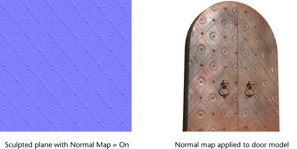
For example, you could arrange several 3D objects to create a normal map of a wall of bricks with window openings, window ledges, or an electrical control panel with gauges and buttons, or a panel effect with recessed grooves for the wing of a spacecraft, and so on.
The saved image can be applied as a normal map in Mudbox or another 3D application.
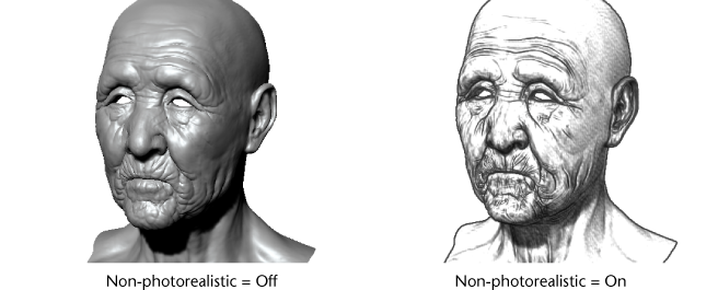
Using the Non-photorealistic filter
The Non-photorealistic effect displays objects in the scene with a hand-drawn, sketch-like appearance. This filter is useful if you want to present your sculpted work so it appears more conceptual in terms of its development.
Depth of Field filter properties
Cavity Ambient Occlusion filter properties
Ambient Occlusion filter properties


